be spur, spiral, hypoid beveled, or worm gears, as
illustrated in figure 13-17.
The function of the final drive is to change by 90
degrees the direction of the power transmitted through
the propeller shaft to the driving axles. It also provides
a fixed reduction between the speed of the propeller
shaft and the axle shafts and wheels. In passenger cars
this reduction varies from about 3 to 1 to 5 to 1. In trucks,
it can vary from 5 to 1 to as much as 11 to 1.
The gear ratio of a final drive having bevel gears is
found by dividing the number of teeth on the drive gear
by the number of teeth on the pinion. In a worm gear
final drive, you find the gear ratio by dividing the
number of teeth on the gear by the number of threads on
the worm.
Most final drives are of the gear type. Hypoid gears
(fig. 13-17) are used in passenger cars and light trucks
to give more body clearance. They permit the bevel
drive pinion to be put below the center of the bevel drive
gear, thereby lowering the propeller shaft. Worm gears
allow a large speed reduction and are used extensively
in larger trucks. Spiral bevel gears are similar to hypoid
gears. They are used in both passenger cars and trucks
to replace spur gears that are considered too noisy.
DIFFERENTIALS
Chapter 11 described the construction and principle
of operation of the gear differential. We will briefly
review some of the high points of that chapter here and
describe some of the more common types of gear
differentials applied in automobiles and trucks.
The purpose of the differential is easy to understand
when you compare a vehicle to a company of sailors
marching in mass formation. When the company makes
a turn, the sailors in the inside file must take short steps,
almost marking time, while those in the outside file must
take long steps and walk a greater distance to make the
turn. When a motor vehicle turns a comer, the wheels
outside of the turn must rotate faster and travel a greater
distance than the wheels on the inside. That causes no
difficulty for front wheels of the usual passenger car
because each wheel rotates independently on opposite
ends of a dead axle. However, to drive the rear wheel at
different speeds, the differential is needed. It connects
the individual axle shaft for each wheel to the bevel
drive gear. Therefore, each shaft can turn at a different
speed and still be driven as a single unit. Refer to the
illustration in figure 13-18 as you study
discussion on differential operation.
the following
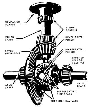
Figure 13-18.-Differential with part of case cut away.
The differential described in chapter 11 had two
inputs and a single output. The differential used in the
automobile has a single input and two outputs. Its input
is introduced from the propeller shaft and its outputs
goes to the rear axles and wheels.
The bevel drive pinion, connected to the pinion
shaft, drives the bevel drive gear and the differential case
to which it is attached. Therefore, the entire, differential
case always rotates with the bevel drive gear whenever
the pinion shaft is transmitting rotary motion. Within the
case, the differential pinions (refereed to as spider gears
in chapter 11) are free to rotate on individual shafts
called trunnions. These trunnions are attached to the
walls of the differential case. Whenever the case is
turning, the differential pinions must revolve-one
about the other-in the same plane as the bevel drive
gear.
The differential pinions mesh with the side gears, as
did the spider and side gears in the differential described
in chapter 11. The axle shafts are splined to the
differential side gears and keyed to the wheels. Power
is transmitted to the axle shafts through the differential
pinions and the side gears. When resistance is equal on
each rear wheel, the differential pinions, side gears, and
axle shafts all rotate as one unit with the bevel drive gear.
In this case, there is no relative motion between the
13-15