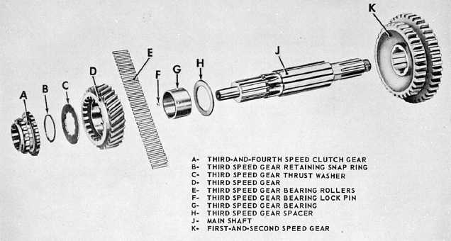
Figure 13-8.—Dissembled main shaft assembly.
(fig. 13-8, A) toward the third-speed gear (fig. 13-8,
D). This action engages the external teeth of the
clutch gear with the internal teeth of the third-speed
gear. Since the third-speed gear is rotating with the
rotating counter-shaft gear, the clutch gear also must
rotate. The clutch gear is splined to the main shaft,
and therefore, the main shaft rotates with the clutch
gear. This principle is carried out when the shift
lever moves from one speed to the next.
Constant-mesh gears are seldom used for all
speeds. Common practice is to use such gears for the
higher gears, with sliding gears for first and reverse
speeds, or for reverse only. When the shift is made to
first or reverse, the first and reverse sliding gear is
moved to the left on the main shaft. The inner teeth
of the sliding gear mesh with the main shaft first
gear.
SYNCHROMESH TRANSMISSION
The synchromesh transmission is a type of
constant-mesh transmission. It synchronizes the
speeds of mating parts before they engage to allow
the selection of gears without their clashing. It
employs a combination metal-to-metal friction cone
clutch and a dog or gear positive clutch. These
clutches allow the main drive gear and second-speed
main shaft gear to engage with the transmission
main shaft. The friction cone clutch engages first,
bringing the driving and driven members to the same
speed, after which the dog clutch engages easily
without clashing. This process is accomplished in one
continuous operation when the driver declutches and
moves the control lever in the usual manner. The
construction of synchromesh transmissions varies
somewhat with different manufacturers, but the
principle is the same in all.
The construction of a popular synchromesh clutch
is shown in figure 13-9. The driving member consists
of a sliding gear splined to the transmission main
shaft with bronze internal cones on each side. It is
surrounded by a sliding sleeve having internal teeth
that are meshed with the external teeth of the sliding
gear. The sliding sleeve has grooves around the
outside to receive the shift fork. Six spring-loaded
balls in radially drilled holes in the gear fit into an
internal groove in the sliding sleeve. That prevents
the sliding sleeve from moving endwise relative to the
gear until the latter has reached the end of its travel.
The driven members are the main drive gear and
second-speed main shaft gear. Each has external
cones and external teeth machined on its sides to
engage the internal cones of the sliding gear and the
internal teeth of the sliding sleeve.
The synchromesh clutch operates as follows: when
the driver moves the transmission control lever to the
third-speed, or direct-drive, position the shift fork
moves the sliding gear and sliding sleeve forward as a
unit until the internal cone on the sliding gear
engages the external cone on the main drive gear.
This action brings the two gears to the same speed
and stops endwise travel of the sliding gear. The
sliding sleeve slides over the balls and silently
engages the external teeth on the main drive gear.
This action locks the main drive gear and
transmission main shaft together as shown in
13-8


