Chapter 4—REDUCTION GEARS AND RELATED EQUIPMENT
grooved to accommodate the rings. As they glide
through the reservoir of oil at the bottom, the
rings carry some of the oil along to the top of the
shaft journal.
On some steam driven ships, the most recent
line shaft bearing design employs oiler discs
instead of oiler rings for lubrication. At very low
speeds (i.e., when the shaft is jacked for 24 hours
while the turbines are cooling), the oil rings tend
to slip and lubrication is sometimes inadequate.
The oiler discs are clamped to propulsion shaft
and have cavities at the periphery which carry oil
to the top of the bearing regardless of the shaft
speed.
Spring bearing temperatures and oil levels
should be checked hourly while underway. At
least once each year, the bearings should be
inspected, clearances taken, and any defects
corrected.
STERN TUBE AND STERN
TUBE BEARINGS
The hole in the hull structure for accom-
modating the propeller shaft to the outside of the
hull is called the stern tube. The propeller shaft
is supported in the stern tube by two bearings—
one at the inner end and one at the outer end of
the stern tube—called stern tube bearings. At the
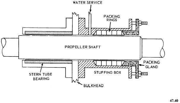
inner end of the stern tube there is a stuffing box
containing the packing gland (figure 4-4), which
is generally referred to as the stern tube gland.
The stern tube gland seals the area between the
shaft and stern tube but allows the shaft to rotate.
The stuffing box is flanged and bolted to the
stern tube. Its casing is divided into two
compartments—the forward space which is the
stuffing box proper, and the after space, provided
with a flushing connection, designed to maintain
a positive flow of water through the stern tube
for lubricating, cooling, and flushing. This
flushing connection is supplied by the firemain.
A DRAIN CONNECTION is provided both for
testing for the presence of cooling water in the
bearing and for permitting sea water to flow
through the stern tube and cool the bearing when
underway, where natural seawater circulation is
employed.
The gland for the stuffing box is divided
longitudinally into two parts. The gland bolts are
long enough to support the gland when the latter
is withdrawn at least 1 inch clear of the stuffing
Figure 4-4.—Stern tube stuffing box and gland.
4-9


