l
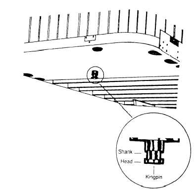
Figure 7-16.—Trailer kingpin.
Go under the trailer and look into the back of the
fifth wheel. Ensure the fifth wheel locking jaws
have closed around the shank of the kingpin
(fig. 7-16).
l
l
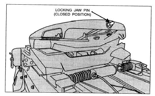
Check that the locking lever pin is in the “lock”
position (fig. 7-17).
Ensure the safety catch is in position over the
locking lever pin (if so equipped).
Step 12. Connect the electrical cord and check air
l
l
l
lines
Plug the electrical cord into the trailer (fig. 7-18)
and fasten the safety catch.
Inspect both air lines and electrical lines for signs
of damage.
Ensure air and electrical lines do not contact any
moving parts of the vehicle.
Step 13. Raise landing gear
l
l
l
Use the low gear (if so equipped) to begin raising
the landing gear. Once free of weight, switch to
the high gear range.
Raise the landing gear all the way up. Driving
with the landing gear part way up is not a good
practice because it may catch on railroad tracks
or other obstacles.
Secure the crank handle safely after the landing
gear is raised.
Figure 7-17.—Locked fifth wheel.
7-16