Figure 1-31.—Blower air intake system.
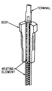
Figure 1-30.-Glow plug.
GLOW PLUGS.— Glow plugs (fig. 1-30) and the
injection nozzle are installed in the precombustion
chamber of the cylinder head. The glow plug is turned
on when you turn on the ignition switch. On some equip-
ment a light on the dashboard signals that the glow plug
is cycling which signals you to wait between 15 to 30
seconds before cranking the engine. The heat, created
by electrical resistance in the glow plug, heats the fuel
and air mixture. The heat generated by the glow plug and
the heat generated by compression allow the fuel to ignite.
AIR INDUCTION SYSTEMS
The function of an air intake system is to supply the
correct amount of air needed to increase the combustion
and the efficiency of an engine. On a diesel engine, the
air intake system cleans the intake air, silences the intake
noise, furnishes air for supercharging, and supplies
scavenged air in two-stroke engines.
The three major components of the air induction
system are blowers, turbochargers, and superchargers.
They may be of the centrifugal or rotary type, or they
may be gear-driven directly from the engine, belt or
chain-driven, or driven by the flow of exhaust gases
from the engine.
BLOWERS
The scavenging process, used in the two-stroke
cycle diesel engine, is simply a charge of air forced into
the cylinder by the blower. As this charge of air is forced
into the cylinder, all the burnt gases are swept out
through the exhaust valve ports. This air also helps cool
the internal engine parts, particularly the exhaust valves.
1-22
The blower shown in figure 1-31 provides the
forced-air induction for the scavenging process. Two
rotors are closely fitted in a housing that is bolted to the
engine. The rotor lobes provide continuous and uniform
displacement of air as the rotors revolve. Blower rotors
either have two lobes or three lobes, depending on the
type.
TURBOCHARGERS
The four-stroke cycle engine uses two methods of
air induction: naturally aspirated and turbo charged. The
naturally aspirated system depends on atmospheric
pressure to keep a constant supply of air in the intake
manifold. The turbocharger is designed to force air into
the cylinder and aid in scavenging the exhaust gases.
The turbocharger differs from the blower in that the
turbocharger uses the energy of exhaust gases to drive
a turbine wheel (fig. 1-32).
The hot exhaust gases from the engine go through
the exhaust inlet, across the turbine wheel, and out the
exhaust outlet. The force of the exhaust turns the turbine
wheel and shaft. This action rotates the compressor
wheel (impeller) that is attached to the opposite end of
the turbine shaft. As the impeller rotates, it draws air into
the housing. The air is then compressed and forced into
the intake manifold.
SUPERCHARGERS
Superchargers are engine-driven air pumps that
force the air and fuel mixture into the engine. They are
made in three basic configurations: centrifugal, Roots,
and vane.