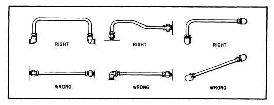
contraction. Bends are preferred to elbows,
because bends cause less of a power loss. A few
of the correct and incorrect methods of installing
tubing are illustrated in figure 5-1.
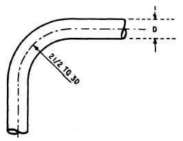
Bends are described by their radius measure-
ments. The ideal bend radius is 2 1/2 to 3 times
the ID, as shown in figure 5-2. For example, if
the ID of a line is 2 inches, the radius of the bend
should be between 5 and 6 inches.
While friction increases markedly for sharper
curves than this, it also tends to increase up to
a certain point for gentler curves. The increases
in friction in a bend with a radius of more than
3 pipe diameters result from increased turbulence
near the outside edges of the flow. Particles of
fluid must travel a longer distance in making the
change in direction. When the radius of the bend
is less than 2 1/2 pipe diameters, the increased
pressure loss is due to the abrupt change in the
direction of flow, especially for particles near the
inside edge of the flow.
During your career in the Navy, you may be
required to fabricate new tubing to replace
damaged or failed lines. Fabrication of tubing
consists of four basic operations: cutting,
deburring, bending, and joint preparation.
Tube Cutting and Deburring
The objective of cutting tubing is to produce
a square end that is free from burrs. Tubing may
be cut using a standard tube cutter (fig. 5-3), a
chipless cutter (fig. 5-4), or a fine-toothed
hacksaw if a tube cutter is not available.
When you use the standard tube cutter, place
the tube in the cutter with the cutting wheel at the
point where the cut is to be made. Apply light
pressure on the tube by tightening the adjusting
Figure 5-2.—Ideal bend radius.
knob. Too much pressure applied to the cutting
wheel at onetime may deform the tubing or cause
excessive burrs. Rotate the cutter toward its open
side (fig. 5-3). As you rotate the cutter, adjust the
tightening knob after each complete turn to
maintain light pressure on the cutting wheel.
When you use the chipless cutter, take the
following steps:
1. Select the chipless cutter according to
tubing size.
2. Rotate the cutter head to accept the tubing
in the cutting position. Check that the cutter
ratchet is operating freely and that the cutter wheel
is clear of the cutter head opening (fig. 5-4).
3. Center the tubing on two rollers and the
cutting blade.
4. Use the hex key provided with the
turn the drive screw in until the cutter
touches the tube.
Figure 5-1.—Correct and incorrect methods of installing tubing.
5-4
kit to
wheel