CHAPTER 9
RESERVOIRS, STRAINERS, FILTERS,
AND ACCUMULATORS
Fluid power systems must have a sufficient
and continuous supply of uncontaminated fluid
to operate efficiently. As stated in chapter 3 and
emphasized throughout this manual, the fluid
must be kept free of all foreign matter.
This chapter covers hydraulic reservoirs,
various types of strainers and filters, and
accumulators installed in fluid power systems.
RESERVOIRS
A hydraulic system must have a reserve of
fluid in addition to that contained in the pumps,
actuators, pipes, and other components of the
system. This reserve fluid must be readily available
to make up losses of fluid from the system, to
make up for compression of the fluid under
pressure, and to compensate for the loss of
volume as the fluid cools. This extra fluid is
contained in a tank usually called a reservoir. A
reservoir may sometimes be referred to as a sump
tank, service tank, operating tank, supply tank,
or base tank.
In addition to providing storage for the reserve
fluid needed for the system, the reservoir acts as
a radiator for dissipating heat from the fluid and
as a settling tank where heavy particles of
contamination may settle out of the fluid and
remain harmlessly on the bottom until removed
by cleaning or flushing of the reservoir. Also, the
reservoir allows entrained air to separate from the
fluid.
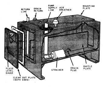
Most reservoirs have a capped opening for
filling, an air vent, an oil level indicator or dip
stick, a return line connection, a pump inlet or
suction line connection, a drain line connection,
and a drain plug (fig. 9-1). The inside of the
reservoir generally will have baffles to prevent
excessive sloshing of the fluid and to put a
partition between the fluid return line and the
pump suction or inlet line. The partition forces
the returning fluid to travel farther around the
tank before being drawn back into the active
Figure 9-1.—Nonpressurized reservoir (ground or ship
installation).
system through the pump inlet line. This aids in
settling the contamination and separating the air
from the fluid.
Large reservoirs are desirable for cooling. A
large reservoir also reduces recirculation which
helps settle contamination and separate air. As
a ‘‘thumb rule,” the ideal reservoir should be two
to three times the pump output per minute.
However, due to space limitations in mobile and
aerospace systems, the benefits of a large reservoir
may have to be sacrificed. But, they must be large
enough to accommodate thermal expansion of the
fluid and changes in fluid level due to system
operation. Reservoirs are of two general types—
nonpressurized and pressurized.
NONPRESSURIZED RESERVOIRS
Hydraulic systems designed to operate
equipment at or near sea level are normally
equipped with nonpressurized reservoirs. This
includes the hydraulic systems of ground and ship
9-1