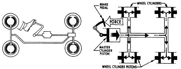
automobiles operates in a way similar to thesystem illustrated in figure 2-22.When the brake pedal is depressed, thepressure on the brake pedal moves the pistonwithin the master cylinder, forcing the brake fluidfrom the master cylinder through the tubing andflexible hose to the wheel cylinders. The wheelcylinders contain two opposed output pistons,each of which is attached to a brake shoe fittedinside the brake drum. Each output piston pushesthe attached brake shoe against the wall of thebrake drum, thus retarding the rotation of thewheel. When pressure on the pedal is released, thesprings on the brake shoes return the wheelcylinder pistons to their released positions. Thisaction forces the displaced brake fluid backthrough the flexible hose and tubing to the mastercylinder.The force applied to the brake pedal producesa proportional force on each of the outputpistons, which in turn apply the brake shoesfrictionally to the turning wheels to retardrotation.As previously mentioned, the hydraulic brakesystem on most automobiles operates in a similarway, as shown in figure 2-22. It is beyond thescope of this manual to discuss the various brakesystems.Figure 2-22.—An automobile brake system.2-17
Integrated Publishing, Inc. - A (SDVOSB) Service Disabled Veteran Owned Small Business