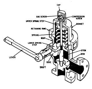
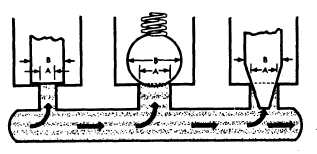
Smaller relief valves, similar in design andoperation to the main system relief valve, are oftenused in isolated parts of the system where a checkvalve or directional control valve prevents pressurefrom being relieved through the main system reliefvalve and where pressures must be relieved at aset point lower than that provided by the mainsystem relief. These small relief valves are alsoused to relieve pressures caused by thermalexpansion (see glossary) of the fluids.Figure 6-11 shows a typical relief valve. Systempressure simply acts under the valve disk at theinlet to the valve. When the system pressureexceeds the force exerted by the valve spring, thevalve disk lifts off of its seat, allowing some ofthe system fluid to escape through the valve outletuntil the system pressure is reduced to just belowthe relief set point of the valve.All relief valves have an adjustment forincreasing or decreasing the set relief pressure.Some relief valves are equipped with an adjustingscrew for this purpose. This adjusting screw isusually covered with a cap, which must beremoved before an adjustment can be made. Sometype of locking device, such as a lock nut, isusually provided to prevent the adjustment fromchanging through vibration. Other types of reliefvalves are equipped with a handwheel for makingadjustments to the valve. Either the adjustingscrew or the handwheel is turned clockwise toincrease the pressure at which the valve will open.In addition, most relief valves are also providedFigure 6-11.—Relief valve.with an operating lever or some type of device toallow manual cycling or gagging the valve openfor certain tasks.Various modifications of the relief valveshown in figure 6-11 are used to efficiently servethe requirements of some fluid power systems;however, this relief valve is unsatisfactory forsome applications. To give you a better under-standing of the operation of relief valves, we willdiscuss some of the undesirable characteristics ofthis valve.A simple relief valve, such as the oneillustrated in figure 6-11, with a suitable springadjustment can be set so that it will open whenthe system pressure reaches a certain level, 500psi for example. When the valve does open, thevolume of flow to be handled may be greater thanthe capacity of the valve; therefore, pressure inthe system may increase to several hundred psiabove the set pressure before the valve brings thepressure under control. A simple relief valve willbe effective under these conditions only if it is verylarge. In this case, it would operate stiffly and thevalve element would chatter back and forth. Inaddition, the valve will not close until the systempressure decreases to a point somewhat below theopening pressure.The surface area of the valve element must belarger than that of the pressure opening if thevalve is to seat satisfactorily as shown in figure6-12. The pressure in the system acts on the valveelement open to it. In each case in figure 6-12,the force exerted directly upward by systempressure when the valve is closed depends on thearea (A) across the valve element where theelement seats against the pressure tube. Themoment the valve opens, however, the upwardforce exerted depends on the horizontal area (B)of the entire valve element, which is greater thanarea A. This causes an upward jump of the valveelement immediately after it opens, because theFigure 6-12.—Pressure acting on different areas.6-7
Integrated Publishing, Inc. - A (SDVOSB) Service Disabled Veteran Owned Small Business