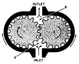
MOTORScontrolled by either a four-way directional controlvalve or a variable-displacement pump.A fluid power motor is a device that convertsfluid power energy to rotary motion and force.The function of a motor is opposite that of apump. However, the design and operation offluid power motors are very similar to pumps.Therefore, a thorough knowledge of the pumpsdescribed in chapter 4 will help you understandthe operation of fluid power motors.Motors have many uses in fluid powersystems. In hydraulic power drives, pumps andmotors are combined with suitable lines and valvesto form hydraulic transmissions. The pump,commonly referred to as the A-end, is driven bysome outside source, such as an electric motor.The pump delivers fluid to the motor. The motor,referred to as the B-end, is actuated by this flow,and through mechanical linkage conveys rotarymotion and force to the work. This type of powerdrive is used to operate (train and elevate) manyof the Navy’s guns and rocket launchers.Hydraulic motors are commonly used to operatethe wing flaps, radomes, and radar equipment inaircraft. Air motors are used to drive pneumatictools. Air motors are also used in missiles toconvert the kinetic energy of compressed gas intoelectrical power, or to drive the pump of ahydraulic system.Fluid motors may be either fixed or variabledisplacement. Fixed-displacement motors provideconstant torque and variable speed. The speed isvaried by controlling the amount of input flow.Variable-displacement motors are constructed sothat the working relationship of the internal partscan be varied to change displacement. Themajority of the motors used in fluid powersystems are the fixed-displacement type.Although most fluid power motors are capableof providing rotary motion in either direction,some applications require rotation in only onedirection. In these applications, one port of themotor is connnected to the system pressure line andthe other port to the return line or exhausted tothe atmosphere. The flow of fluid to the motoris controlled by a flow control valve, a two-waydirectional control valve, or by starting andstopping the power supply. The speed of themotor may be controlled by varying the rate offluid flow to it.In most fluid power systems, the motor isrequired to provide actuation power in eitherdirection. In these applications the ports arereferred to as working ports, alternating as inletand outlet ports. The flow to the motor is usuallyFluid motors are usually classified accordingto the type of internal element, which is directlyactuated by the flow. The most common types ofelements are the gear, the vane, and the piston,AU three of these types are adaptable for hydraulicsystems, while only the vane type is used inpneumatic systems.GEAR-TYPE MOTORSThe spur, helical, and herringbone designgears are used in gear-type motors. The motorsuse external-type gears, as discussed in chapter 4.The operation of a gear-type motor is shownin figure 10-12. Both gears are driven gears;however, only one is connected to the outputshaft. As fluid under pressure enters chamber A,it takes the path of least resistance and flowsaround the inside surface of the housing, forcingthe gears to rotate as indicated. The flowcontinues through the outlet port to the return.This rotary motion of the gears is transmittedthrough the attached shaft to the work unit.The motor shown in figure 10-12 is operatingin one direction; however, the gear-type motor iscapable of providing rotary motion in eitherdirection. To reverse the direction of rotation, theports may be alternated as inlet and outlet. Whenfluid is directed through the outlet port (fig. 10-12)into chamber B, the gears rotate in the oppositedirection.Figure 10-12.—Gear-type motor.10-8
Integrated Publishing, Inc. - A (SDVOSB) Service Disabled Veteran Owned Small Business