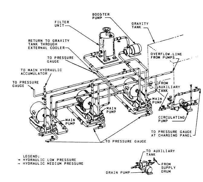
For more detailed information concerning thesymbols used in fluid power diagrams, consult theabove-mentioned military standards. Additionalinformation concerning symbols and the readingof diagrams is contained in BIueprint Reading andSketching, NAVEDTRA 10077-F1.TYPES OF DIAGRAMSThere are many types of diagrams. Those thatare most pertinent to fluid power systems arediscussed in this text.Pictorial DiagramsPictorial diagrams (fig. 12-1) show thegeneral location and actual appearance of eachcomponent, all interconnecting piping, and thegeneral piping arrangement. This type of diagramis sometimes referred to as an installationdiagram. Diagrams of this type are invaluable tomaintenance personnel in identifying and locatingcomponents of a system.Cutaway DiagramsCutaway diagrams (fig. 12-2) show the internalworking parts of all fluid power components ina system. This includes controls and actuatingmechanisms and all interconnecting piping.Cutaway diagrams do not normally use symbols.Figure 12-1.—Hydraulic system pictorial diagram.12-2
Integrated Publishing, Inc. - A (SDVOSB) Service Disabled Veteran Owned Small Business