shrouding over the blade tips and the rotor drum area
under the stator vanes. tip rubs of either the blades or
the vanes will rub off the aluminum coating. As time is
accrued on the compressor assembly, the after stages of
the rotor release or flake the aluminum coating. This
deterioration is a normal progression. Flaking occurs
because of the differences in thermal expansion of
dissimilar metals and the differences in the size and
configuration of the various parts. The released
aluminum flakes enter the airstream, impact the rotor
blades or vanes, and splatter the airfoils. Aluminum
splatter observed forward of stage 11 can be caused by
object damage or aluminum flakes that are rubbed out
of the compressor case coating. This condition requires
a thorough inspection of the forward compressor stages.
Leading Edge Buildup.— Aluminum buildup on
the leading edges of blades is usually observed in stages
11 through 16. The buildup changes the contour of the
airfoil and can alter the stall margin. You should report
the presence of leading edge buildup in the inspection
report. This type of buildup may occur on low-time
compressors.
The compressor blades tend to “self
clean” or lose this leading edge buildup as the assembly
accrues time.
Airfoil Powdering.— Compressor rotor blades may
have aluminum particles visible on the airfoils in
varying degrees (from stage to stage). This powder is
indicative of a possible compressor stall or a hard blade
tip rub.
Combustion Section
Inspect the combustor for eroded or burned areas,
cracks, nicks, dents, hot streaks, flatness of liners caused
by hot spots, blocked air passages, and carbon buildup.
If damage is found in the combustion section, it usually
consists of a burn-through in the dome area adjacent to
a fuel nozzle. The problem can usually be traced to a
loss of film-cooling air caused by upstream debris or to
a faulty fuel nozzle.
Cracking is not normally a
problem, but you should photograph and report any
suspected or confirmed cracks. Carbon deposits around
the fuel nozzles occur on all engines and are not
considered serious. These deposits build up only on the
venturi and swirl cup rather than on the shroud or
discharge orifice. They do not usually interfere with the
fuel spray pattern. If you find cracking, evaluate it to
ensure that no pieces will detach and cause any
secondary damage to the HP turbine. For reference to
parts nomenclature used in the following section, refer
to figure 2-11, sections B and C.
COMBUSTION SECTION DAMAGE.— In the
following paragraphs, we describe some of the damage
that you might find during a borescope inspection of the
combustion section. Because the dark surfaces in the
combustion section absorb light, you will need a
1,000-watt light source for a proper inspection.
Discoloration. — Normal aging of the combustor
components will show a wide range of color changes.
This is not a cause for concern. As operating time is
accrued on the combustor assembly, an axial streaking
pattern running aft of every other circumferential fuel
nozzle will occur.
On low-time assemblies, the
coloration is random and has little or no information to
aid you during the inspection. As operating time
increases on the assembly, you will observe significant
deterioration at the edges of the streaking patterns.
Cracking will begin in the forward inner liner panels and
will propagate aft. The axial cracks tend to follow the
light streaks. Panel overhang cracking and liberation
usually occur at the edge of the streaks.
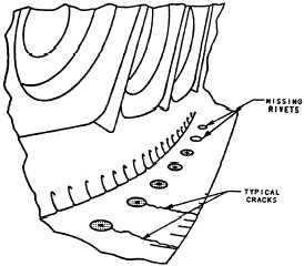
Riveted Joints.— The dome band and the inner and
outer liner assemblies are joined by rivets as shown in
figure 2-18. The presence and condition of the rivet
heads and rivet holes are easily assessed because of their
position in relationship to the borescope ports. Record
any missing rivets and torn or cracked hole edges.
Dome Assembly. — Distortion of the trumpets
and/or swirl cups is random and occurs on high-time
assemblies. Record the distortion (in percent) of the
edge and/or span of the trumpet and the percent of
circumference versus diameter of the swirlers.
Figure 2-18.—Combustion liner dome rivet joint.
2-15