If the defect shows at a point one-half of the
distance along the base line (fig. 11-11) from the
entrance peak, then the defect will actually lie one-half
of the thickness of the piece from the entrance surface.
If the piece is 1 inch thick, then the defect will lie 1/2
inch below the surface. If the defect peak is high, the
defect is large (in a plane 90 from the beam); and if the
peak is small, then the defect is small. If the defect is
larger than the beam diameter, the defect surface will
bounce back ALL the beam, and the back reflection
peak will disappear. If the defect is smaller than the
beam diameter, some of the beam will be stopped and
bounced by the defect, and some will go on and be
bounced by the back of the piece. The CRT will then
show the near-surface peak, the small intermediate
peak, and a slightly reduced peak (at the back or far side
of the piece) at the right, or designated l-inch point, on
the base line.
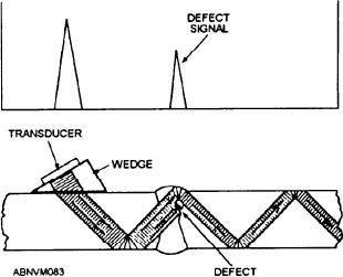
Figure 11-12.--Angle beam testing.
Calibration Block
wedge to the transducer. This is known as the angle
beam method, shown in figure 11-12.
You need to determine the size of a defect, and
where possible, evaluate the nature of the defect.
As you can see in figure 11-12, the sound beam
This means that some reference or standard for
passes through the wedge and enters the part to be
tested at an angle. The sound beam will continue
absolutely necessary. The most common practice is
to bounce at this angle until it is completely
to use a sample piece of material with a hole drilled
scattered or absorbed by the material. Weld
in it and compare defect signals obtained from the
inspections are performed when the sound has
made only one or two bounces. If a flaw is present
part of ultrasonic testing, since it is essentially a
in the weld, as indicated in figure 11-12, some of
comparison test.
the sound beam will reflect back and show up as an
indication on the CRT screen.
The best scanning method is to move the
ULTRASONIC WELD INSPECTION
search unit forward and backward. Alternately
approach and move away from the weld a
Detecting, locating, and measuring defects are the
distance sufficient to permit the sound to pass
major requirements for weld inspection.
through the full thickness of the plate and the
When testing welds for defects, you should use
weld in an upward and downward path. The
search unit is also moved parallel to the weld
This is easily done if the defects have a boundary
itself, as shown in figure 11-13. In this manner,
that lies parallel to the plane upon which the
you will scan the complete volume of the weld,
transducer rests, and the face of the transducer lies
following the same pattern along the weld, as
flat upon that plane. Such placement results in a
shown by the dotted line in figure 11-13.
longitudinal (compressional) beam with its axis
normal to the surface boundary. To obtain the
NONDESTRUCTIVE TESTING
surface boundary or defect boundary that lies at
SYMBOLS
right angles to its direction of travel. Since most
weld defects are rotated 90 from the surface, you
Nondestructive testing symbols specify the type of
will need a way to change the direction of the
test to be used and the extent to which the test will be
sound beam. You can do this by securing a Lucite
11-14


