
Figure 7-12.--Indexing equipment.
The workpiece may be held in a chuck or a collet,
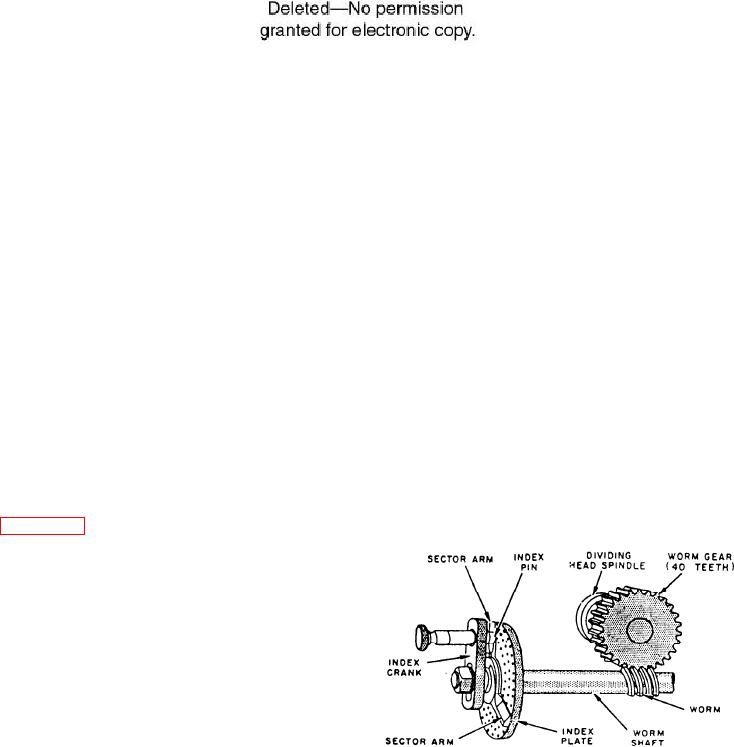
can turn the dividing head spindle one of two ways:
attached to the dividing head spindle, or held between
Do it directly by hand by disengaging the worm and
a live center in the dividing index head and a dead
drawing the plunger back, or by the index crank
center in the footstock. The center of the footstock
through the worm and worm gear.
can be raised or lowered to set up tapered workpieces.
The spindle is set in a swivel block so you can set
The center rest can be used to support long slender
the spindle at any angle from slightly below
work.
horizontal to slightly past vertical. We said earlier
Figure 7-13 shows the internal components of the
dividing head. The ratio between the worm and the
gear is 40 to 1. By turning the worm one turn, you
rotate the spindle 1/40 of a revolution. The index
plate has a series of concentric circles of holes. You
can use these holes to gauge partial turns of the worm
shaft and to turn the spindle accurately in amounts
smaller than 1/40 of a revolution. You can secure the
index plate either to the dividing head housing or to a
rotating shaft and you can adjust the crankpin radially
for use in any circle of holes. You can also set the
sector arms as a guide to span any number of holes in
the index plate to provide a guide to rotate the index
Figure 7-13.--Dividing head mechanism.
crank for partial turns. To rotate the workpiece, you
7-9

