
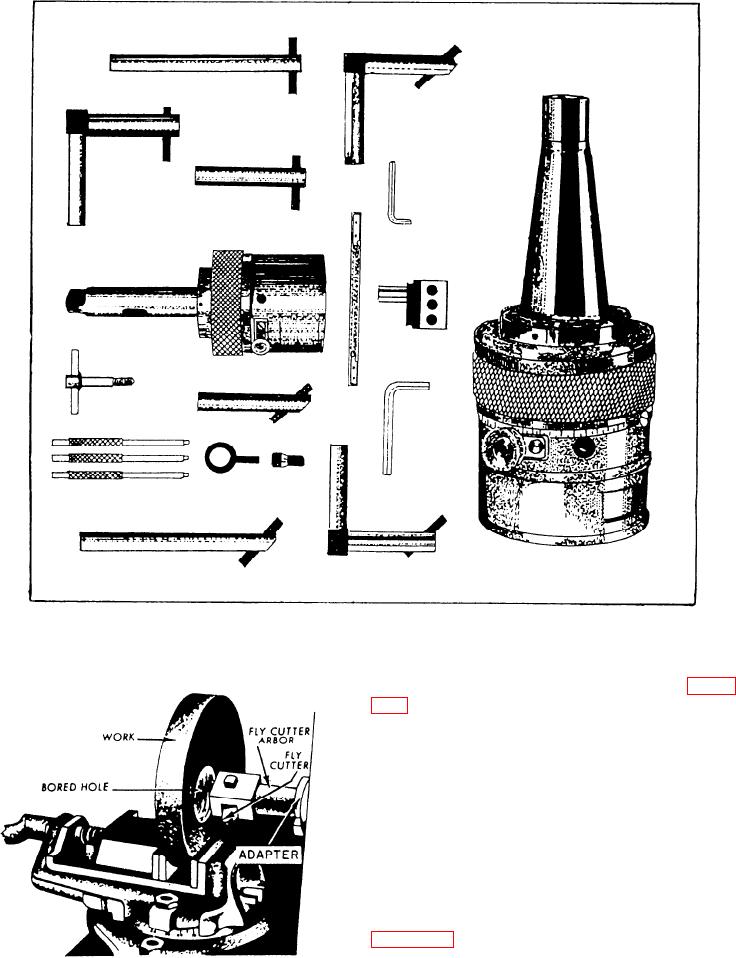
Figure 7-76.--Offset boring head and boring tools.
usually bore holes with an offset boring head. Figure
7-76 shows several views of an offset boring head and
several boring tools. Note that the chuck jaws, which
grip the boring bar, can be adjusted at a right angle to
the spindle axis. This feature lets you accurately
position the boring cutter to bore holes of varying
diameters. This adjustment is more convenient than
adjusting the cutter in the boring bar holder or by
changing boring bars.
Although the boring bars are the same on a
milling machine as on a lathe or drill press, the
manner in which they are held is different. Note in
figure 7-77 that a boring bar holder is not used. The
boring bar is inserted into an adapter and the adapter
is fastened in the hole in the adjustable slide. Power
Figure 7-77.--Boring with a fly cutter.
to drive the boring bar is transmitted directly through
the shank. The elimination of the boring bar holder
7-46

