
TM 55-2815-574-24
0047
REMOVAL - Continued
NOTE
Twelve-point washer head bolts with "LE" head identification must be discarded upon
removal.
9.
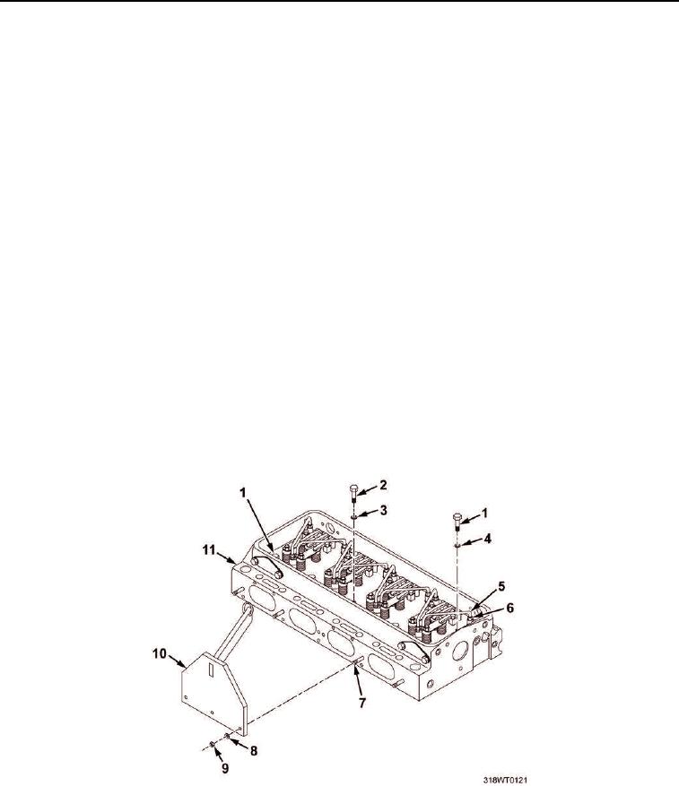
Remove eight side bolts (Figure 2, Item 2) and washers (Figure 2, Item 3), and discard if necessary.
10.
Install lifting fixture (Figure 2, Item 10) to three exhaust manifold studs (Figure 2, Item 7) with washers
(Figure 2, Item 8) and nuts (Figure 2, Item 9).
11.
Attach lifting sling to lifting fixture (Figure 2, Item 10) and make taut.
NOTE
Twelve-point washer head bolts with "LE" head identification must be discarded upon
removal.
12.
Remove two corner bolts (Figure 2, Item 1) and washers (Figure 2, Item 4), and discard if necessary.
13.
Position wood wedges on bench for setting cylinder head (Figure 2, Item 11).
14.
Lift and remove cylinder head (Figure 2, Item 11).
CAUTION
Cylinder head must be set on wooden blocks, positioned lengthwise, to prevent damage to
cam followers. Failure to comply may result in damage to equipment.
15.
Carefully position valve side of cylinder head (Figure 2, Item 11) on bench on wood blocks.
16.
Remove lifting fixture (Figure 2, Item 10) from cylinder head (Figure 2, Item 11).
Figure 2. Cylinder Head Fuel Line Removal.

