Chapter 8—ENVIRONMENTAL POLLUTION
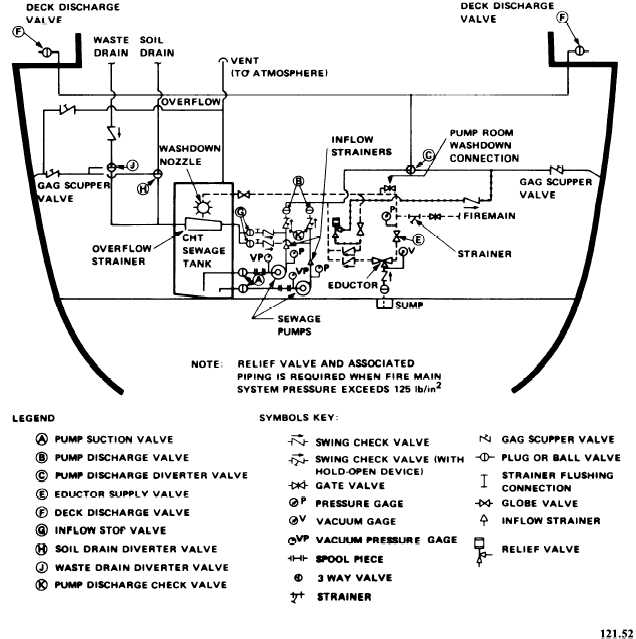
Figure 8-6.—Strainer-type CHT system.
should be fitted where required to protect the
hose. Care should be taken to prevent the hose
from snagging between the ship and the pier.
Valves A, B, and C should be lined up and
set for discharge to the shore side deck discharge
at valve F. The receiving station sewer valve
should then be opened, followed by valve F at the
deck connection. With a person stationed at deck
connection F, pass the word to the CHT pump
room that hose connections have been made (see
figures 8-5 and 8-6).
Set both pump controller selector switches to
AUTO position. Set soil drain diverter valves H
and waste drain diverter valves J to the CHT
COLLECTION position for drainage to the CHT
tank. After the tank is pumped down and the
8-17