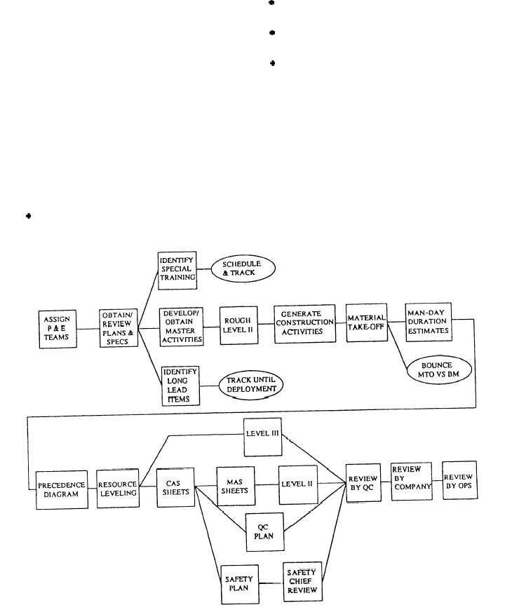
A flow chart, showing the sequence of planning
steps, is shown in figure 15-2. These steps are
also listed in the project planning milestones list
(fig. 15-3). This list is normally assigned by the
operations department at the beginning of home port.
Step-by-step information on how a project package is
developed is outlined in the Naval Mobile Construc-
tion Battalion Crewleader’s Handbook, C O M-
SECOND/COMTHIRDNCBINST 5200.2X.
PROJECT DRAWINGS
In the NCF, project drawings are normally divided
into the following major categories: civil, architec-
tural, structural, mechanical, and electrical.
Regardless of the category, project drawings serve
the following functions:
. They provide a basis for estimating material,
labor, and equipment before construction begins.
. They provide precise instructions for construc-
tion, showing the sizes and locations of various parts.
. They provide a means of coordination between
the different ratings.
l They complement the specifications; one source
of information is incomplete without the other.
Pages
Most drawings have sheets/pages with designator
letters (I—Index, C
—Civil, A—Architectural,
S—Structural, M—Mechanical, P—Plumbing,
E—Electrical, and W—Waterfront). For example, as
shown in figure 15-4, the sheet designating letter and
page number is the 22d architectural page in a set of
plans, so it is written A-22. The name, or title, of the
project will be in the largest block on the page. For EO
Figure 15-2.—Project planning flow chart.
15-3