aft doors’ cylinders and the shuttle valve on the
nose gear cylinder to close off the normal port
and operate these cylinders. The nose gear cylinder
extends; this unlocks the uplock and extends the
nose gear. The nitrogen flowing into the aft door
cylinders opens the aft doors. Fluid on the close
side of the door cylinder is vented to return
through the actuated dump valves. Nitrogen from
another bottle actuates the shuttle valves on the
uplock cylinders. Nitrogen flows into the uplock
cylinders and causes them to disengage the
uplocks. As soon as the uplocks are disengaged,
the main gear extends by the force of gravity.
Fluid on the up side of the main gear cylinders
is vented to return through the actuated dump
valves, preventing a fluid lock.
JET BLAST DEFLECTORS
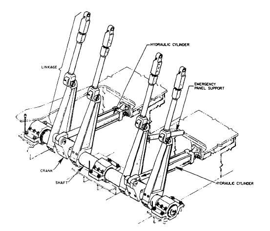
Jet blast deflectors (JBD) onboard aircraft
carriers are raised and lowered by hydraulic
cylinders through mechanical linkage. Two
hydraulic cylinders are attached to each JBD panel
shaft by crank assemblies. (See fig. 12-9.) The
shaft is rotated by the push and pull operation
of the hydraulic cylinders. Shaft rotation extends
or retracts the linkage to raise or lower the JBD
panels. This operation is designed so that in the
event of a failure of one of the hydraulic cylinders,
the other one will raise or lower the panels.
Figure 12-10 is a diagram of the hydraulic
control system of a JBD during the raise cycle.
Hydraulic fluid from the catapult hydraulic supply
system is supplied to the JBD hydraulic system
through an isolation valve and a filter to the 4-way
control valve assembly. (The 4-way control valve
assembly consists of a pilot-operated control
valve, a direct- or solenoid-operated control valve,
and a sequence valve, which is not shown.)
To raise the JBD, solenoid B of the 4-way
control valve assembly is energized. The spools
of the 4-way valve assembly shift, allowing
medium-pressure hydraulic fluid to flow into port
A of the hydraulic cylinder. The cylinders extend,
Figure 12-9.—Operating gear assembly (panels raised).
12-10