
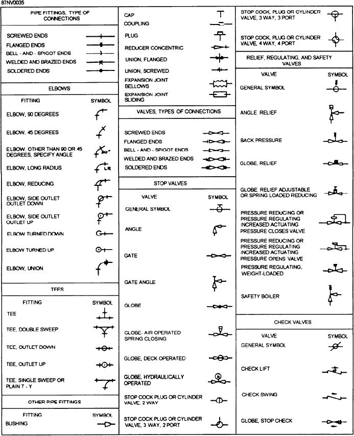
pieces of equipment. Figure 15-36 shows some of the
should have a wide knowledge of shipboard piping
symbols generally used in engineering plans and
systems.
diagrams. There may be slight differences on some
Symbols make it easier to show piping systems on
drawings; but, in general, the symbols will be like those
paper. These symbols represent the valves and other
illustrated. These symbols will help you to understand
Figure 15-36.--Symbols used in engineering plans and diagrams.
15-38