
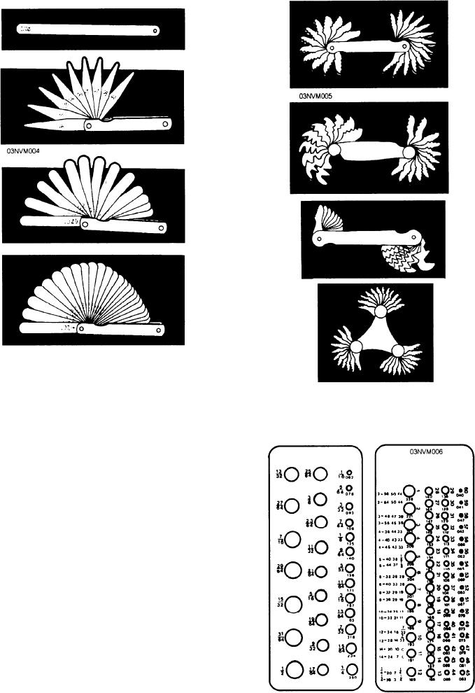
Figure 5-4.--Thickness (feeler) gauges.
Figure 5-5.--Screw-pitch gauges.
more blades may be combined to take readings of
various thicknesses.
Screw-Pitch Gauges
Screw-pitch gauges (fig. 5-5) are made for checking
the pitch of U.S. Standard, Metric, National Form, and
V-form cut threads. You will use them to determine the
correct thread pitch of an unknown thread on a bolt,
inside a nut, or in choosing the correct tap or die for
threading stock or tapping a hole. Each thread gauge is
marked in number of threads per inch. To take a meas-
urement, simply lay the gauge on the thread. The correct
gauge will fit the thread of the bolt perfectly with no
light showing between the gauge and the threads of the
bolt. The pitch of the screw thread is the distance
between the center of one tooth to the center of the next
tooth.
Drill Gauges
The twist drill and drill rod gauge has a series
of holes with size and decimal equivalents stamped
adjacent to each hole, as shown in figure 5-6. Drill
gauges use either a letter, number, decimal, or fraction
Figure 5-6.--Drill gauges.
5-5