

in the opposite direction. Since the two bevel
gears (G and H) are fixed on the shaft
with F, they also turn. These bevel
gears, meshing with the horizontal bevel gears (I
and J), cause I and J to swing the front ends of the
telescopes to the right. Thus with a simple system of
gears, it is possible to keep the two telescopes
pointed at a moving target. In this and
many other applications, gears serve one
purpose: to change the direction of
motion. GEARS USED TO
CHANGE SPEED As youve already
seen in the eggbeater, you use gears to
change the speed of motion. Another example
of this use of gears is in your clock or watch. The
mainspring Slowly unwinds
and causes the hour hand to make one
revolution in 12 hours. Through a series-or
train-of gears, the minute hand makes one
revolution each hour, while the second
hand goes around once per minute.
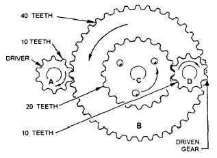
Figure 6-9 will help you to understand how
speed changes are possible. Wheel A
has 10 teeth that mesh with the 40
teeth on wheel B. Wheel A will have to rotate
four times to cause B to make one revolution. Wheel C
is rigidly fixed on the same shaft with B. Thus, C
makes the same number of revolutions as
B. However, C has 20 teeth and meshes
with wheel D, which has only 10 teeth.
Hence, wheel D turns twice as fast as wheel C.
Now, if you turn A at a speed of four revolutions per
second, B will rotate at one revolution per
second. Wheel C also moves at one
revolution per second and causes D
to turn at two revolutions per second. You get
out two revolutions per second after having put in
four revolutions per second.
Thus, the overall speed
reduction is 2/4or 1/2that means you got half the
speed out of the last driven wheel you put into the
first driver wheel.
You can solve any gear speed-reduction problem
with this formula:
Figure 6-9.-Gears can change speed of applied motion.
Now use the formula on the gear train of figure 6-9.
To obtain any increase or decrease in speed you,
must choose the correct gears for the job. For
example, the turbines on a ship have to
turn at high speeds-say 5,800 rpmif
they are going to be efficient. The
propellers, or screws, must turn rather slowlysay
195 rpmto push the ship ahead with maximum
efficiency. So, you place a set of reduction
gears between the turbines and the
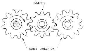
propeller shaft. When two external
gears mesh, they rotate in
opposite directions. Often youll want to avoid this. Put
a third gear, called an idler, between the driver and
the driven gear. Dont let this extra
gear confuse you on speeds. Just
neglect the idler entirely. It doesnt change
the gear ratio at all, and the formula still applies. The idler
merely makes the driver and its driven gear turn in
the same direction. Figure 6-10 shows
you how this works. where
=
=
=
=
speed of first shaft in train
speed of last shaft in train
product of teeth on all drivers
product of teeth on all driven gears
Figure 6-10.-An idler gear.
6-5


