the NCF, are governed by a pressure control system,
adjusted to compress air to a maximum pressure of
100 pounds per square inch (psi). Compressor units are
available in reciprocating, rotary, or screw design.
Compressors are classified as either single-stage or
multistage. A single-stage compressor has one
compressing element that compresses the air from the
initial intake pressure to the final discharge pressure in one
step. The multistage compressor has more than one
compressing element. The first stage compresses the air
to an intermediate pressure, then through one or more
additional stages to final discharge pressure. The
multistage system is more efficient than the single-stage
system, because the air cooling that occurs between stages
reduces buildup of pressure due to a temperature rise.
All military construction compressors are governed
by a pressure control system. In a reciprocating
compressor, this control system causes the engine to
idle and the suction valve to remain open when the
pressure reaches a set maximum. When the air pressure
drops below a set minimum, the pressure control system
causes the engine to increase speed and the suction valve
to close, starting the compression cycle again. The
rotary compressor output is governed by varying the
engine speed. The engine operates automatically at the
speed needed to compress enough air to supply the
demand at a fairly constant pressure. When the engine
has slowed to idle because of low demand, a valve
throttles the amount of free air that may enter the
compressor.
The screw compressor output is controlled
automatically and provides a smooth, uninterrupted
capacity from full load to no load in response to the
demand for air. This capacity is achieved by a floating
speed engine control and a variable inlet compressor.
COMPRESSOR CAPACITY
The capacity of an air compressor is determined by
the amount of free air (at sea level) that it can compress
to a specified pressure, usually 100 psi per minute, under
the conditions of 68°F and a relative humidity of 38
percent. This capacity is expressed in cubic feet per
minute (cfm) and is usually included in the
nomenclature of the compressor.
The number of pneumatic tools that can be operated
at one time from an air compressor depends on the air
requirements of each tool; for example, a 55-pound class
rock drill requires 95 cfm of air at 80 psi. A 210-cfm
compressor can supply air to operate two of the drills,
because their combined requirements is 190 cfm.
However, if a third such drill is added to the compressor,
the combined demand is 285 cfm, and this condition
overloads the compressor and the tools and results in
serious wear.
NOTE: When the pressure and volume of air to a
pneumatic tool drops 10 percent below the designed
minimum, the tool efficiency is reduced 41 percent.
Compressor Location
Install the compressor unit so it is as close to level
as possible. Compressor design permits a 15-degree
lengthwise and a 15-degree sidewise limit on
out-of-level operation. The engine, not the compressor,
is the limiting factor. When the unit is to be operated
out of level, you should be sure to do the following:
1. Keep the engine crankcase oil level on the full
mark with the unit level.
2. Ensure the compressor oil gauge shows full with
the unit level.
Compressed Air System
A compressed air system consists of one or more
compressors, each with the necessary power source,
regulation, intake air filter, aftercooler, air receiver,
connecting piping, and a distribution system to carry the
air to points of use.
The object of installing a
compressed air system is to provide enough air at the
work area at pressures adequate for efficient operation
of pneumatic tools.
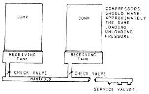
Many construction jobs require more cfm than one
compressor can produce. Also, terrain conditions often
create problems of distance from the compressor to the
operating tool. Since the air line hose causes a loss of
pressure (friction loss) at distances farther than 200 feet,
a system has been devised for efficient transmission of
compressed air over longer distances. This system is air
manifolding (fig. 14- 10).
Figure 14-10.—Methods of manifolding compressors.
14-8