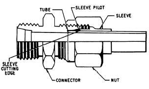
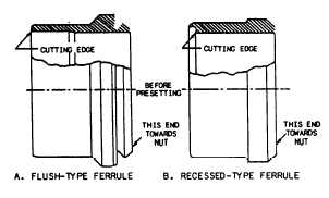
FLARELESS-TUBE CONNECTORSThis type of connector eliminates all tubeflaring, yet provides a safe, strong, and depend-able tube connection. This connector consistsof a fitting, a sleeve or ferrule, and a nut.(See fig. 5-18.)NOTEAlthough the use of flareless tubeconnectors is widespread, NAVSEA policyis to reduce or eliminate use of flarelessfittings in newly designed ships; the extentto which flareless fittings are approved foruse in a particular ship is reflected inapplicable ship drawings.Flareless-tube fittings are available in manyof the same shapes and thread combinations asflared-tube fittings. (See fig. 5-16.) The fitting hasa counterbore shoulder for the end of the tubingto rest against. The angle of the counterborecauses the cutting edge of the sleeve or ferrule tocut into the outside surface of the tube when thetwo are assembled.The nut presses on the bevel of the sleeve andcauses it to clamp tightly to the tube. Resistanceto vibration is concentrated at this point ratherthan at the sleeve cut. When fully tightened, thesleeve or ferrule is bowed slightly at the midsectionand acts as a spring. This spring action of thesleeve or ferrule maintains a constant tensionbetween the body and the nut and thus preventsthe nut from loosening.Prior to the installation of a new flareless-tubeconnector, the end of the tubing must be square,Figure 5-18.—Flareless-tube connector.concentric, and free of burrs. For the connectionto be effective, the cutting edge of the sleeve orferrule must bite into the periphery of the tube(fig. 5-19). This is ensured by presetting the sleeveor ferrule on the tube.PresettingPresetting consists of deforming the ferrule tobite into the tube OD and deforming the end ofthe tube to form a shallow conical ring seatingsurface. The tube and ferrule assembly should bepreset in a presetting tool that has an end sectionidentical to a fitting body but which is made ofspecially hardened steel. This tool hardness isneeded to ensure that all deformation at the tubeend seat goes into the tube.Presetting is done with a hydraulic presettingtool or a manual presetting tool, either in the shopor aboard ship. The tool vendor’s instructionsmust be followed for the hydraulic presetting tool.If a presetting tool is not available, the fittingbody intended for installation is used in the samemanner as the manual presetting tool. (If analuminum fitting is used, it should not be reusedin the system.) The manual tool is used as follows:WARNINGFailure to follow these instructions mayresult in improperly preset ferrules withinsufficient bite into the tube. Improperlypreset ferrules have resulted in joints thatpassed hydrostatic testing and operated forweeks or years, then failed catastrophicallyunder shock, vibration, or normal operat-ing loads. Flareless fitting failures haveFigure 5-19.—Unused ferrules.5-15
Integrated Publishing, Inc. - A (SDVOSB) Service Disabled Veteran Owned Small Business