A simple manifold is illustrated in figure 5-24.
This manifold contains one pressure inlet port and
several pressure outlet ports that can be blocked
off with threaded plugs. This type of manifold
can be adapted to systems containing various
numbers of subsystems. A thermal relief valve
may be incorporated in this manifold. In this case,
the port labeled T is connected to the return line
to provide a passage for the relieved fluid to flow
to the reservoir.
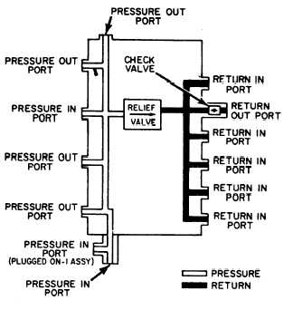
Figure 5-25 shows a flow diagram in a
manifold which provides both pressure and return
passages. One common line provides pressurized
fluid to the manifold, which distributes the fluid
to any one of five outlet ports. The return side
of the manifold is similar in design. This manifold
is provided with a relief valve, which is connected
to the pressure and return passages. In the event
of excessive pressure, the relief valve opens and
allows the fluid to flow from the pressure side of
the manifold to the return side.
Figure 5-25.—Fluid manifold—flow diagram.
PRECAUTIONARY MEASURES
The fabrication, installation, and maintenance
of all fluid lines and connectors are beyond the
scope of this training manual. However, there are
some general precautionary measures that apply
to the maintenance of all fluid lines.
Regardless of the type of lines or connectors
used to make up a fluid power system, make
certain they are the correct size and strength and
perfectly clean on the inside. All lines must be
absolutely clean and free from scale and other
foreign matter. Iron or steel pipes, tubing, and
fittings can be cleaned with a boiler tube
wire brush or with commercial pipe cleaning
apparatus. Rust and scale can be removed from
short, straight pieces by sandblasting, provided
there is no danger that sand particles will remain
lodged in blind holes or pockets after the piece
Figure 5-24.—Fluid manifold.
5-20


