
TM 55-2815-574-24
SUSTAINMENT MAINTENANCE
ENGINE
FUEL INJECTOR TIMING ADJUSTMENT
INITIAL SETUP:
Tools and Special Tools
Equipment Condition (cont.)
General mechanic's tool kit
Main navigation mast removed
(WP 0179, Table 1, Item 130)
(TM 55-1945-205-10)
Injector timing gauge (WP 0179, Table 1, Item 48)
Intake plenum assembly removed
(TM 55-1925-205-10)
Operator's cab removed (TM 55-1925-205-10)
Personnel Required
Powered section engine hatch removed
Engineer 88L (2)
(TM 55-1925-205-23)
Crankcase breather limiter assembly removed
Equipment Condition
Air inlet collector assembly removed (WP 0104)
Engine cool to touch
Air intake housing assembly removed (WP 0103)
Single channel ground and airborne radio system
Cylinder head poppet valve rocker arm cover
(SINCGARS) antenna removed
removed (WP 0044)
(TM 11-5820-890-10-8)
ADJUSTMENT
NOTE
This task is typical for all injectors on both port and starboard engines.
No-fuel position can be obtained by fully rotating fuel rod clevis away from
electronic governor actuator.
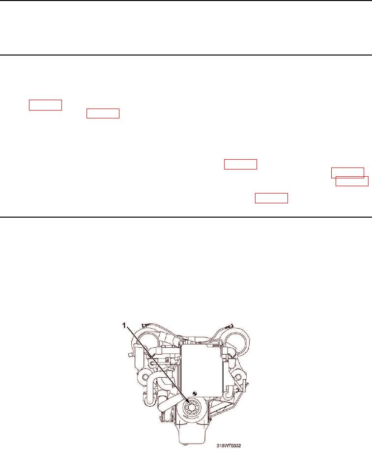
1.
First engineer will rotate crank shaft (Figure 1, Item 1) clockwise while second engineer holds fuel rod clevis
(Figure 2, Item 1) in no-fuel position.
Figure 1. Crankshaft.
2.
Second engineer will tell first engineer when exhaust valves (Figure 2, Item 2) are in full open position.