
TM 55-2815-574-24
SUSTAINMENT MAINTENANCE
ENGINE
FUEL PUMP REPAIR
INITIAL SETUP:
Tools and Special Tools
Materials/Parts (cont.)
General mechanic's tool kit
Adhesive (WP 0178, Table 1, Item 3)
(WP 0179, Table 1, Item 130)
Cleaning compound (WP 0178, Table 1, Item 9)
Air filtering respirator (WP 0179, Table 1, Item 109)
Engine lubricating oil, 10W
Chemical gloves (WP 0179, Table 1, Item 52)
(WP 0178, Table 1, Item 24)
Fuel pump tool kit (WP 0179, Table 1, Item 129)
Gasket (WP 0180, Table 1, Item 75)
Hammer (WP 0179, Table 1, Item 61)
Seal (WP 0180, Table 1, Item 19)
Hand operated arbor press
Softwood lumber, dimension, 2 in. x 4 in. x 6 ft
(WP 0179, Table 1, Item 97)
min wooden blocks Qty: 2
Industrial goggles (WP 0179, Table 1, Item 54)
(WP 0178, Table 1, Item 27)
Machinists vise (WP 0179, Table 1, Item 133)
Socket wrench set, 3/8 in. sqdr.
Personnel Required
(WP 0179, Table 1, Item 135)
Engineer 88L
Torque wrench, 150750 in-lb (1785 Nm)
(WP 0179, Table 1, Item 142)
Materials/Parts
Abrasive cloth (WP 0178, Table 1, Item 12)
WARNING
Use caution when using a hammer or chisel. Flying particles or debris may be present.
Wear protective goggles. Failure to comply may result in personnel injury or death.
DISASSEMBLY
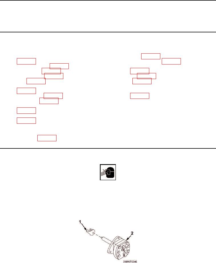
1.
Remove drive coupling fork (Figure 1, Item 1) from pump (Figure 1, Item 2).
Figure 1. Drive Coupling Fork Disassembly.