
TM 55-2815-574-24
0072
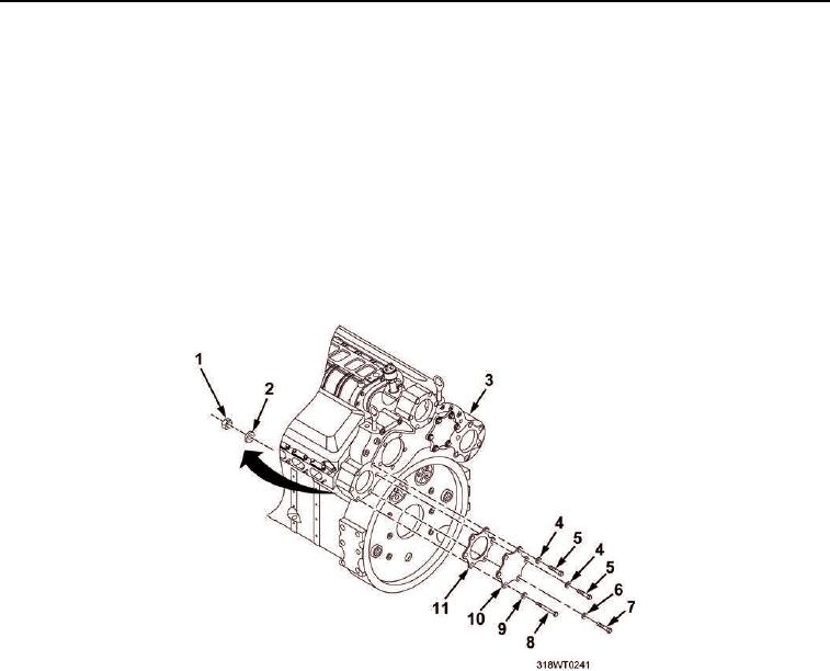
INSTALLATION - Continued
22.
Apply ultra blue sealing compound to flywheel housing (Figure 20, Item 3) and access plate
(Figure 20, Item 10).
23.
Install new gasket (Figure 20, Item 11) on flywheel housing (Figure 20, Item 3).
24.
Install cap screws (Figure 20, Item 7) and new lockwashers (Figure 20, Item 6) through access cover
(Figure 20, Item 10) and into flywheel housing (Figure 20, Item 3).
25.
Install two cap screws (Figure 20, Item 5) and new lockwashers (Figure 20, Item 4) through access cover
(Figure 20, Item 10) and into flywheel housing (Figure 20, Item 3).
26.
Install three cap screws (Figure 20, Item 8), copper washers (Figure 20, Item 9), new lockwashers
(Figure 20, Item 2) and hex nuts (Figure 20, Item 1) through access cover (Figure 20, Item 10) and into
flywheel housing (Figure 20, Item 3).
Figure 20.