
TM 55-2815-574-24
0108
REMOVAL - Continued
3.
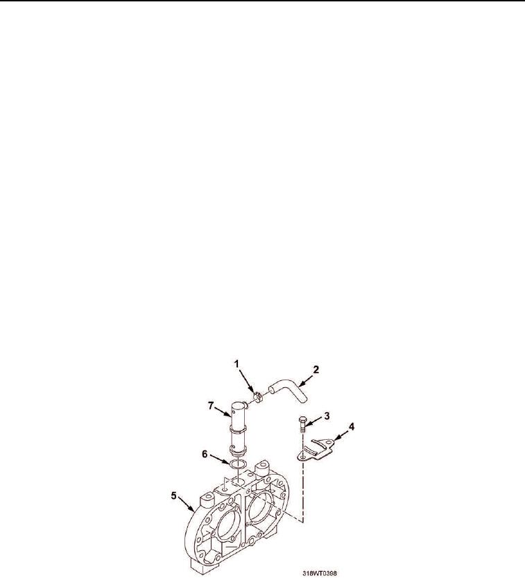
Squeeze open clamp (Figure 2, Item 1) and slide back onto hose (Figure 2, Item 2).
4.
Remove hose (Figure 2, Item 2) from valve (Figure 2, Item 7).
5.
Remove bolts (Figure 2, Item 3) from collar (Figure 2, Item 4).
6.
Remove collar (Figure 2, Item 4) from end plate (Figure 2, Item 5).
7.
Remove valve (Figure 2, Item 7) from blower end plate (Figure 2, Item 5) and discard valve
(Figure 2, Item 7).
8.
Remove and discard ring seal (Figure 2, Item 6) from blower end plate (Figure 2, Item 5).
END OF TASK
INSTALLATION
1.
Install new ring seal (Figure 2, Item 6) in blower end plate (Figure 2, Item 5).
2.
Push new valve (Figure 2, Item 7) into blower end plate (Figure 2, Item 5).
3.
Install collar (Figure 2, Item 4) onto blower end plate (Figure 2, Item 5).
4.
Install bolts (Figure 2, Item 3) securing collar (Figure 2, Item 4) to blower end plate (Figure 2, Item 5).
5.
Tighten bolts (Figure 2, Item 3).
6.
Install hose (Figure 2, Item 3) onto valve (Figure 2, Item 7).
7.
Install clamp (Figure 2, Item 1) over hose (Figure 2, Item 2) and valve (Figure 2, Item 7).
Figure 2. Blower Bypass Valve.
8.
Remove LO/TO from A3 breaker switch (Figure 1, Item 1). Refer to FM 4-01.502 for LO/TO procedure.
END OF TASK