TM 55-2815-574-24
0122
REMOVAL - Continued
c.
Remove and discard gasket (Figure 1, Item 17).
3.
Remove two support brackets (Figure 1, Item 14) as follows:
a.
Remove two bolts (Figure 1, Item 10) and two washers (Figure 1, Item 11) securing two support
brackets (Figure 1, Item 14) to main bearing cap (Figure 1, Item 12).
b.
Separate the two legs of each support bracket (Figure 1, Item 14) by removing one bolt
(Figure 1, Item 9), two washers (Figure 1, Item 8), and one nut (Figure 1, Item 15) from slotted hole.
END OF TASK
CLEANING
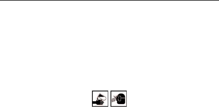
WARNING
Compound may cause irritation to eyes or skin. In case compound comes in contact with
eyes or skin, immediately flush eyes with water, wash skin with soap and water. Wear
protective goggles, gloves, and clothing. Failure to comply may result in personnel injury
or death.
1.
Using cleaner and clean cloth, clean screen (Figure 1, Item 5) of dirt, grease, oil, and other foreign matter.
2.
Using cleaner and clean cloth, clean all hoses, fittings, nuts, bolts, and tube assembly (Figure 1, Item 1).
END OF TASK
INSPECTION
1.
Inspect screen (Figure 1, Item 5) for broken, missing or damaged screening. Replace as necessary.
2.
Inspect tube assembly (Figure 1, Item 1) for dents, cracks, and foreign objects that are obstructing tube.
Replace tube as necessary.
END OF TASK
INSTALLATION
1.
Install two support brackets (Figure 1, Item 14) as follows:
a.
Connect two legs of each support bracket (Figure 1, Item 14) by installing one bolt (Figure 1, Item 9),
two washers (Figure 1, Item 8) and one nut (Figure 1, Item 15) in slotted hole.
b.
Attach two support brackets (Figure 1, Item 14) to main bearing cap (Figure 1, Item 12) with two bolts
(Figure 1, Item 10) and two washers (Figure 1, Item 11).
2.
Attach tube assembly (Figure 1, Item 1) to oil pump housing (Figure 1, Item 16) as follows:
a.
Place new gasket (Figure 1, Item 17) on oil pump housing (Figure 1, Item 16).
b.
Place forward end of tube assembly (Figure 1, Item 1) over gasket (Figure 1, Item 17) and opposite
end of support brackets (Figure 1, Item 14).
c.
Secure tube assembly (Figure 1, Item 1) to oil pump housing (Figure 1, Item 16) with two bolts
(Figure 1, Item 19) and two new lockwashers (Figure 1, Item 18).
0122-3


