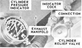
only on engines installed on small boats. Engines
like the GM-6-71 do not have indicator cocks
installed.
When taking compression readings on a 6-71
engine, you will perform the following steps:
1. Check the manufacturer’s technical manual
for the minimum compression pressure required
for the engine.
2. Start the engine and run it at approximately
one-half the rated load until normal operating
temperatures are reached.
3. Stop the engine and remove the fuel pipes
from the injector and the fuel connectors on the
cylinder to be tested.
4. Remove the injector and install the
indicator adapter, with pressure gage attached,
and use the crab nut to hold the adapter in place.
5. Use a space fuel pipe to fabricate a jumper
connection between the fuel inlet and the return
manifold connectors to by-pass fuel to and from
the injector.
6. Start the engine again and run it at approx-
imately 600 rpm.
7. Observe and record the compression
pressure as indicated on the gage.
Another type of trapped pressure indicator is
the Kiene indicator (figure 3-3). This indicator is
basically a Bourdon gage connected to a cylin-
drical pressure chamber. The pressure chamber
contains a check valve which allows the gas to
ENGINEMAN 1 & C
flow from the engine into the chamber until the
pressures are equalized. This gage is attached to
the chamber and the pressure is read directly. The
check valve is an inverted piston seating on a seat
piece. The valve moves up and down in a guide.
A stop nut is used to adjust the travel of the check
valve.
Most of you should become familiar with this
indicator since it is widely used to check both the
compression and firing pressures on main diesel
engines and emergency generator diesel engines.
Review figure 3-4A and B. It is a PMS situation
requirement to be performed when the engine
operating conditions indicate problems.
EXHAUST AND CYLINDER
TEMPERATURES
One of the most useful tools that the engine
operator has for monitoring an engine’s perform-
ance is the thermocouple pyrometer. The prin-
cipal use of this device is in the exhaust system
(but it can also be used for other purposes) where
it is used to measure the exhaust gas temperatures
at each cylinder or the common temperature in
the exhaust manifold. By comparing the exhaust
gas temperatures of each cylinder, the operator
can determine if the load is balanced throughout
the engine.
The two types of pyrometers in use are the
fixed installation and the portable hand-held
instrument (figure 3-5). Both types use a ther-
mocouple unit, such as the one shown in figure
3-5, installed in the exhaust manifold.
In its simplest form, a thermocouple consists
of two dissimilar metal wires, usually iron and
constantan (55% copper and 45% nickel) that are
joined at both ends to form a continuous circuit.
When the temperatures at the junctions are dif-
ferent an electrical current is produced and flows
in the circuit. The greater the temperature dif-
ference, the greater the voltage produced.
Courtesy of Bacharach, Inc., USA
75.238X
Figure 3-3.—Trapped Pressure Indicator.
One junction, known as the hot junction, is
contained in a closed-end tube, installed in the ex-
haust manifold of each cylinder. The other junc-
tion called the cold junction, is exposed to room
temperature, and is located at the pyrometer wire
3-4


