ENGINEMAN 1 & C
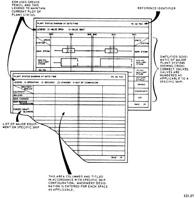
Figure 2-20.—Sample Plant Status Diagram.
delineating the preferred electric power generator
combinations for the various plant operating con-
ditions. This diagram is also provided in the Stage
II electrical documentation.
System alignment diagrams (figure 2-21)
delineating the preferred initial and final align-
ment for each engineering plant.
A diagram for equipment versus speed
requirement delineating the equipment normally
required for various ship speeds.
A diagram for shore services connection
locations delineating the location of shore service
connections for steam, electrical power, feed-
water, potable water, and saltwater, and fuel oil.
2-34

