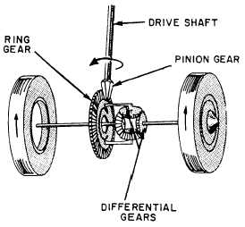
Figure 2-15.-Gears used in final drives.
cars, this reduction varies between 3 to 1 and 5 to 1. In
trucks, it can vary from 5 to 1 to as much as 11 to 1.
The gear ratio of a final drive with bevel gears is
frond by dividing the number of teeth on the driven or
ring gear by the number of teeth on the pinion. In a
worm gear final drive, the gear ratio is found by counting
the number of revolutions of the worm gear for one
revolution of the driven gear.
Most final drives are gear type. Hypoid differential
gears permit a lower body design. They permit the
bevel-driven pinion to be placed below the center of the
ring gear, thereby lowering the propeller shaft, as shown
in figure 2-15.
Worm gears allow a larger speed
reduction and are sometimes used on large trucks.
Spiral bevel gears are similar to hypoid gears and are
used in both passenger cars and trucks to replace spur
gears that are too noisy.
DIFFERENTIALS
Another important unit in the power train is the
differential, which is a type of final drive. As shown in
figure 2-16, the differential is located between the axles
and permits one axle shaft to turn at a different speed
from that of the other. At the same time, the differential
transmits power from the transmission/transfer case to
both axle shafts. The variation in axle shaft speed is
Figure 2-16.—Differential operation.
necessary when the vehicle turns a corner or travels over
uneven ground. As a vehicle travels around a curve, the
outer wheel must travel faster and further than the inner
wheel. Without the differential, one rear wheel would
be forced to skid when turns are made, resulting in
excessive tire wear as well as making the vehicle more
difficult to control.
Some trucks have a differential lock to keep one
wheel from spinning. This is a simple dog clutch,
2-11