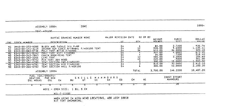
Figure 6-28.—Typical data display for an assembly.
the P-437 is used for these drawings. Volume 1 contains
reproducible engineering drawings and is organized as
follows:
Part 1 (Component Site Plans) is indexed by
component designation and includes typical site plans
for the ABFC components. When a component does not
have a site plan, the word None appears on the data
display for the component.
Part 2 (Facility Drawings and Networks) is
indexed by facility number and contains detailed
construction drawings of the ABFC facilities. Also
included in part 2 preconstruction networks. A network
is a diagram that is used to guide and manage a
construction project. It includes information, such as
6-37
the sequence of construction activities, start and finish
dates of each construction activity, duration of each
activity, and other information that is of use to the crew
leaders, supervisors, and managers of a project. The
Seabee Planner's and Estimator's Handbook, NAVFAC
P-405, provides detailed guidance on reading and
preparing construction networks.
Part 3 (Assembly Drawings) contains working
drawings of the ABFC assemblies. It is indexed by
assembly number.
The above is only a brief overview of Advanced
Base Functional Components. For more information,
you should refer to the NAVFAC P-437, Volume 2.