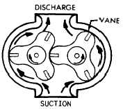
Figure 4-7.—Lobe pump.
previously. The lobes are considerably larger than
gear teeth, but there are only two or three lobes
on each rotor. A three-lobe pump is illustrated
in figure 4-7. The two elements are rotated, one
directly driven by the source of power, and the
other through timing gears. As the elements
rotate, liquid is trapped between two lobes of each
rotor and the walls of the pump chamber and
carried around from the suction side to the
discharge side of the pump. As liquid leaves the
suction chamber, the pressure in the suction
chamber is lowered, and additional liquid is forced
into the chamber from the reservoir.
The lobes are constructed so there is a
continuous seal at the points where they meet at
the center of the pump. The lobes of the pump
illustrated in figure 4-7 are fitted with small vanes
at the outer edge to improve the seal of the pump.
Although these vanes are mechanically held in
their slots, they are, to some extent, free to move
outward. Centrifugal force keeps the vanes snug
against the chamber and the other rotating
members.
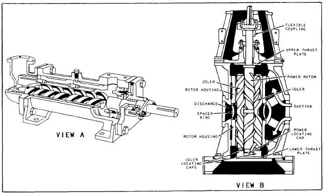
SCREW PUMP
Screw pumps for power transmission systems
are generally used only on submarines. Although
low in efficiency and expensive, the screw pump
is suitable for high pressures (3000 psi), and
delivers fluid with little noise or pressure
pulsation.
Screw pumps are available in several different
designs; however, they all operate in a similar
manner. In a fixed-displacement rotary-type screw
pump (fig. 4-8, view A), fluid is propelled axially
Figure 4-8.—Screw pumps.
4-7