
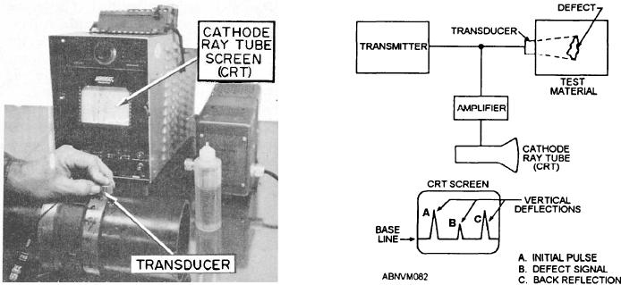
where it is converted back to electrical energy. It is then
ULTRASONIC PRINCIPLE
relayed to an amplifier. The beam is then presented on
The term ultrasonic means vibrations or sound
a cathode ray tube (CRT) screen as vertical deflections
waves whose frequencies are greater than those that
of the base line. Figure 11-11 is a block diagram
affect the human ear (greater than about 20,000 cycles
showing this principle.
per second). The Navy uses equipment that has, for
CRT SCREEN.--The CRT screen shows a base
practical purposes, a frequency range between 500,000
line of light along the lower part of the screen. The
and 10,000,000 cycles per second.
initial pulse bounce between the transducer and the
UT Equipment
metal is shown as a peak rising from this line at the left
or start position. It takes a certain amount of time for a
The UT equipment, shown in figure 11-10, includes
signal or beam to travel through the metal, and
a transmitter/transducer and CRT screen. These are the
approximately the same amount of time to bounce back.
two basic components of all UT equipment regardless
This time is calibrated along the base line as distance,
of make or model.
or as the distance traveled by the beam front in a certain
TRANSDUCER.--High-frequency
electric
time. If a test piece has a certain thickness and no
energy from the transmitter is transformed into
defects, the CRT screen will show the start position peak
high-frequency mechanical energy by the transducer.
somewhere on the left of the base line and another peak
The transducer is held against a piece of metal with
(back reflection) to the right of the base line at a distance
some oil or glycerin (called a couplant) between the
proportional to the thickness of the piece. The
contacting surfaces to prevent air from remaining
relationship of the actual thickness of the test piece to
between them.
the distance shown on the base line may be determined
The high-frequency mechanical energy, in the form
from the calibration settings on the instrument. These
of high-frequency sound, is transmitted into and
two peaks will be relatively high on the screen and will
through the metal. After entering the metal, the sound
represent the beam entrance into the piece and reflection
travels in straight lines in what is known as the beam
from the opposite surface, respectively. If there were a
path. When the beam strikes the far surface of the piece
defect between the two surfaces, SOME of the beam
or strikes the boundary of a defect, the beam reflects
would BOUNCE from the boundaries of the defect and
back toward the transducer. When the beam is
would show on the CRT somewhere along the base line
reflected, it leaves the metal in the same area it entered,
at a distance relative to the two surface indications,
travels through the couplant, and enters the transducer
usually as a smaller peak.
Figure 11-10.--Ultrasonic testing equipment.
Figure 11-11.--Principle of ultrasonics.
11-13