
TM 55-2815-574-24
0130
REMOVAL - Continued
3.
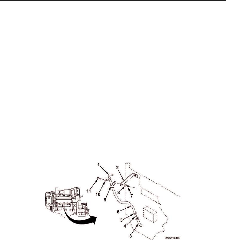
Remove oil level dipstick (Figure 2, Item 1) from lube oil dipstick tube assembly (Figure 2, Item 6).
4.
Remove nut (Figure 2, Item 7), lockwasher (Figure 2, Item 8), washer (Figure 2, Item 10), and bolt
(Figure 2, Item 11) from clamp (Figure 2, Item 9) and bracket (Figure 2, Item 2).
5.
Remove clamp (Figure 2, Item 9) from lube oil dipstick tube assembly (Figure 2, Item 6).
6.
Loosen captive nut (Figure 2, Item 5) and remove lube oil dipstick tube assembly (Figure 2, Item 6) from oil
pan guide (Figure 2, Item 3).
7.
Remove O-ring (Figure 2, Item 4) from lube oil dipstick tube assembly (Figure 2, Item 6).
8.
Discard lube oil dipstick tube assembly (Figure 2, Item 6), and O-ring (Figure 2, Item 4).
END OF TASK
INSTALLATION
1.
Install new O-ring (Figure 2, Item 4) on new lube oil dipstick tube assembly (Figure 2, Item 6).
2.
Install lube oil dipstick tube assembly (Figure 2, Item 6) in oil pan guide (Figure 2, Item 3) and tighten
captive nut (Figure 2, Item 5).
3.
Install clamp (Figure 2, Item 9) on lube oil dipstick tube assembly (Figure 2, Item 6).
4.
Install bolt (Figure 2, Item 11), washer (Figure 2, Item 10), lockwasher (Figure 2, Item 8), and nut
(Figure 2, Item 7) through clamp (Figure 2, Item 9) and engine bracket (Figure 2, Item 2). Tighten nut.
5.
Install oil level dipstick (Figure 2, Item 1) in lube oil dipstick tube assembly (Figure 2, Item 6).
6.
Remove LO/TO from A3 breaker switch. Refer to FM 4-01.502 for LO/TO procedure.
Figure 2. Oil Dipstick.
END OF TASK

