
TM 55-2815-574-24
0129
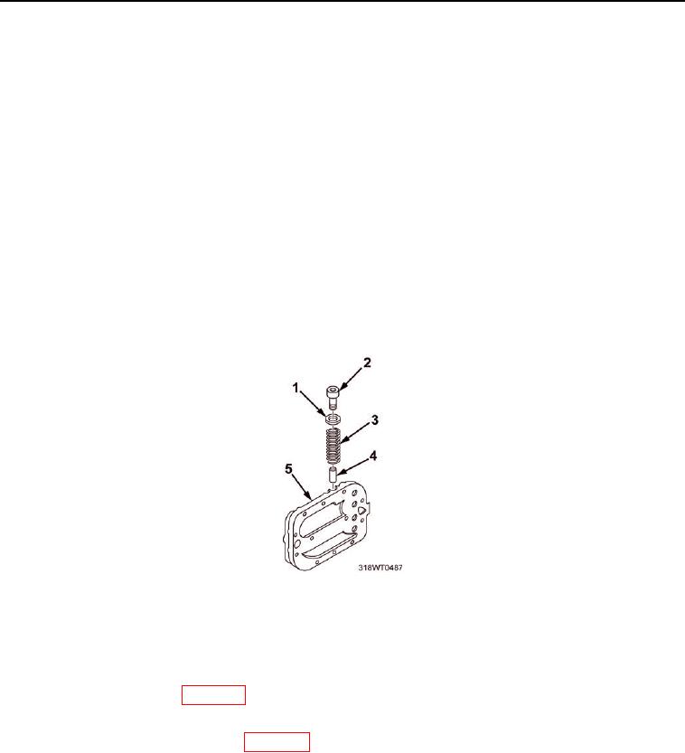
INSTALLATION
1.
Install bypass valve (Figure 1, Item 4) in engine oil cooler adapter (Figure 1, Item 5) valve cavity closed end
first.
NOTE
Ensure the spring is placed inside of the bypass valve on installation.
2.
Install bypass valve spring (Figure 1, Item 3) in engine oil cooler adapter (Figure 1, Item 5) valve cavity .
3.
Install a new gasket (Figure 1, Item 1) on the retaining plug (Figure 1, Item 2).
NOTE
A slotted bypass valve plug is used with engine oil cooler adapter plug on some engines.
Torque this plug to 25 to 30 ft-lb (34 to 41 Nm).
4.
Install retaining plug (Figure 1, Item 2) in engine oil cooler adapter (Figure 1, Item 5) valve cavity and tighten
plug.
5.
Using torque wrench, torque retaining plug (Figure 1, Item 2) to 30 to 40 ft-lb (41 to 54 Nm).
Figure 2. Oil Cooler Adapter.
END OF TASK
FOLLOW-ON MAINTENANCE
1.
Install engine oil cooler (WP 0128).
2.
Install overspeed governor. Contact Maintenance Supervisor.
3.
Install oil cooler mounting bracket (WP 0158).
4.
Install marine gear oil cooler (TM 55-1925-319-23).
5.
Perform operational checks (TM 55-1925-205-10).
END OF TASK
END OF WORK PACKAGE