
TM 55-2815-574-24
0003
AIR INDUCTION SYSTEM - Continued
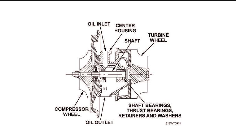
Figure 3. Turbocharger.
Lubricating oil for the turbocharger is supplied under pressure through an external oil line extending from the
engine cylinder block to the top of the center housing. From the oil inlet in the center housing, the oil flows through
the drilled oil passages in the housing to the shaft bearings and thrust bearings. The oil returns by gravity to the
engine oil pan through an external oil line extending from the bottom of the turbocharger center housing to the
cylinder block.
Air Intake Housing
The air intake housing is mounted on the blower. A valve mounted inside of the housing may be closed to shut off
the air supply and stop the engine when abnormal operating conditions require an emergency shut down.