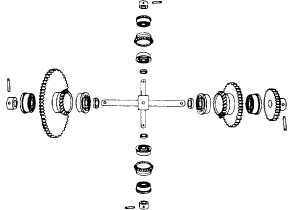
Figure 11-9.-Exploded view of differential gear system.
Other Types of Springs
Torsion bars (fig. 11-7, C) are straight bars that are
acted on by torsion (twisting force). The bars may be
circular or rectangular in cross section. They also may
be tube shaped; other shapes are uncommon.
A special type of spring is a ring spring or disc spring
(not illustrated). It is made of several metal rings or discs
that overlap each other.
THE GEAR DIFFERENTIAL
A gear differential is a mechanism that is capable of
adding and subtracting mechanically. To be more
precise, we should say that it adds the total revolutions
of two shafts. It also subtracts the total revolutions of
one shaft from the total revolutions of another
shaft—and delivers the answer by a third shaft. The gear
differential will continuously and accurately add or
subtract any number of revolutions. It will produce a
continuous series of answers as the inputs change.
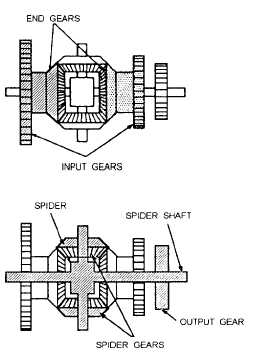
Figure 11-8 is a cutaway drawing of a bevel gear
differential showing all of its parts and how they relate
to each other. Grouped around the center of the
mechanism are four bevel gears meshed together. The
two bevel gears on either side are “end gears.” The two
bevel gears above and below are “spider gears.” The
long shaft running through the end gears and the three
spur gears is the “spider shaft.” The short shaft running
through the spider gears together with the spider gears
themselves make up the “spider.”
Each spider gear and end gear is bearing-mounted
on its shaft and is free to rotate. The spider shaft connects
Figure 11-10.-The differential. End gears and spider
arrangement.
with the spider cross shaft at the center block where they
intersect. The ends of the spider shaft are secured in
flanges or hangers. The spider cross shaft and the spider
shaft are also bearing-mounted and are free to rotate on
their axis. Therefore, since the two shafts are rigidly
connected, the spider (consisting of the spider cross
shaft and the spider gears) must tumble, or spin, on the
axis of the spider shaft.
The three spur gears, shown in figure 11-8, are used
to connect the two end gears and the spider shaft to other
mechanisms. They may be of any convenient size. Each
of the two input spur gears is attached to an end gear. An
input gear and an end gear together are called a “side”
of a differential. The third spur gear is the output gear,
as designated in figure 11-8. This is the only gear pinned
to the spider shaft. All the other differential gears, both
bevel and spur, are bearing-mounted.
Figure 11-9 is an exploded view of a gear
differential showing each of its individual parts. Figure
11-10 is a schematic sketch showing the relationship of
the principle parts. For the present we will assume that
the two sides of the gear system are the inputs and the
gear on the spider shaft is the output. Later we will show
that any of these three gears can be either an input or an
output.
11-7