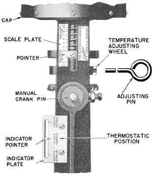
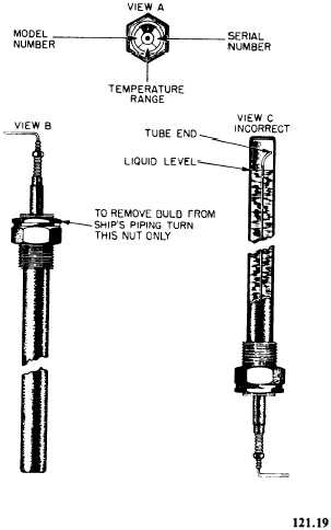
CLOSED, excessive leakage is indicated. In suchcase you will have to regrind the valve using thefollowing procedure:1. Disconnect the valve from the piping.2. Remove the packing nut and the packing.3. Disconnect the valve stem and remove thelocknut from the thermostatic stem.4. Remove the thermostatic control unitfrom the valve.5. Clean the valve stem until it is smooth.If necessary, polish it with fine emery cloth.6. Grind the valve seats until a perfect sealis obtained; then remove all grinding compoundfrom the valve and the seats.7. Reassemble the valve and the control unit.8. Repack the stuffing box and lubricate itwith engine oil.Figure 3-9.—Bulb installation.ENGINEMAN 1 & C9. Secure the packing gland nut finger tight.10. Insert the bulb into the ship’s piping ineither a horizontal or vertical position, as shownin views A and B of figure 3-9. When the bulbis installed in the vertical position, the nut mustbe at the top; when it is installed in the horizon-tal position, the arrow on the indicator disk mustpoint upward. NEVER INSTALL THE BULBWITH THE NUT AT THE BOTTOM (as shownin view C of figure 3-9) because in this positionthe liquid would be below the end of the internalcapillary tube and would have little or no effecton the bellows of the temperature regulator valve.11. Adjust the regulator.AdjustmentA closeup of the adjusting and indicatingfeatures of the temperature regulator is shown infigure 3-10. The procedure for adjusting atemperature regulator is as follows: Rotate themanual crank pin until the indicator pointer is inFigure 3-10.—Scale and Indicator plates of temperatureregulator.3-10
Integrated Publishing, Inc. - A (SDVOSB) Service Disabled Veteran Owned Small Business