power unit, and the relief valves are located at the inside
of the left door. The return and suction filters are located
at the top of the hydraulic tank.
A pressure-compensated valve to change rod rpm
according to drilling conditions is located at the inside
of the left door.
The four pumps provide oil as follows:
l Pump one provides oil for right side tramming
and slow and fast feed drilling.
. Pump two provides oil for left side tramming,
drill, and fast feed.
. Pump three provides oil for high-speed
tramming, rotation, and cooler.
. Pump four provides oil for high-speed tramming,
dust collector, centralizer, cylinders, and auto rod
changer (if so equipped).
Oil Cooler
The oil cooler maintains safe temperatures for
hydraulic oil and compressor oil in all climates and is
located at the top of the power unit. At low
temperatures, the oil bypasses the coder through the
cold bypass valve.
Air System
The air system consists of a compressor air end,
receiver tank, blow air circuit, dust collector (if so
equipped), and air lube system.
The air end is connected to the engine with a flexible
coupling. The compressed air is delivered to the
receiver tank, located at the backside of the power unit.
The compressed air, mixed with compressor oil, is
separated from the oil in the receiver tank and is
distributed to each system. The separated compressor
oil is sent to the oil cooler from the receiver tank under
pressure. The compressor discharge air volume is 230
cfm, and the discharge air pressure is 100 psi.
NOTE: A common cause of low discharge air
pressure is a clogged orifice muffler, located on the
upper rear left comer of the rock drill.
The dust collector is equipped with a stepping pulser
that sends discharged air every 20 seconds to knock off
the cuttings on the filter into the dropout chute, located
at the bottom of the collector.
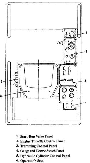
CONTROL CONSOLE
Controls on the drill guide are only for drilling and
cylinder movement.
All other engine controls,
tramming valve, and cylinder valve are located around
the operator’s seat, as shown in figure 14-22.
BOOM
The rock drill is equipped with an expendable boom,
commonly called a mast. The boom can vary 5 feet in
length from the fully retracted to the fully extended
position. The extendable booms are constructed of
square steel tubing with a dump base holder at the front
end and a clevis at the rear end. The clevis is hinged to
a pedestal that is held in the boom base clevis by a
kingpin.
Figure 14-22.—Operator's control console.
14-17


