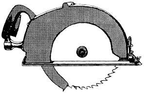
Figure 14-19.—Pneumatic drill.Figure 14-20.—Pneumatic circular saw.. Wear safety shoes, safety glasses or impactgoggles, gloves, hearing protection, and a hard hat.. Never rest an air tool on your toes.. Do not allow horseplay.. Never point an air hose at yourself or others.. Always keep both hands on the handle of the toolwhile operating.. Always bleed the airline before removing it fromthe tool.CRAWLER-MOUNTED ROCK DRILLThis section provides only the basic terminologyand procedures used in rock drilling operations. Theextensive knowledge and skills, required to perform asan effective rock drill operator, must be gained throughformal training or on-the-job-training experience.A component of quarry operations that contains allitems of equipment needed to drill is the crawler-mounted rock drill (fig. 14-21). This drill is a self-propelled unit, designed primarily to drill vertical andangular blast holes in rock.NOTE: Consult the operator’s and maintenance’smanual to obtain information on the type of rock drillyou are assigned.MAIN FRAMEThe main frame is a steel fabrication, designed towithstand the strain imposed by operation over adverseterrain. The main frame provides a mounting base forthe various components of the rock drill.Track oscillation is controlled by two hydrauliccylinders, connected to brackets welded to both sides ofthe main frame and to brackets welded to the trackframe.The cylinders permit 20-percent trackoscillation, dampen sudden oscillation shocks whentramming over rough terrain, and stabilize the unit whensetting up on uneven ground.TRACTION DRIVEThe tracks are driven by a traction device thatconsists of a parking brake, an axial piston motor, abrake valve, and a planet gear reduction. The tractiondrive is equipped with spring-loaded, hydraulicallyreleased brakes. The brakes are released automaticallywhen hydraulic fluid is directed to the motors to movethe unit. Themotors in theuncontrolledbrake valve, located within each of thehydraulic circuit, prevents the unit fromrunaways on grades. Each brake is14-15
Integrated Publishing, Inc. - A (SDVOSB) Service Disabled Veteran Owned Small Business