shops are the Morse taper shank, shown in figures
4-28 and 4-29A and the straight shank, shown in
figures 4-29B and 4-29C.
Twist drills are made from several different
materials. Drills made from high-carbon steel are
available; however, their use is limited by the low
cutting speed required to keep this type of drill from
becoming permanently dull. Most of the twist drills
that you will use are made from high-speed steel and
will have two flutes (fig. 4-28).
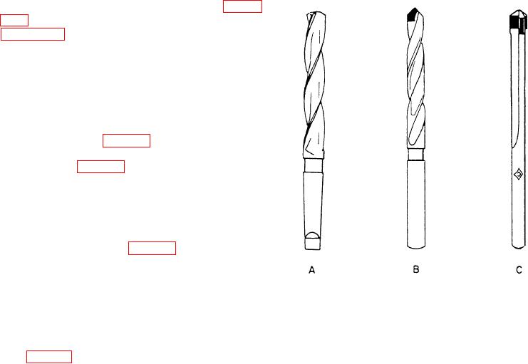
Core drills (fig. 4-29A) have three or more flutes
and are used to enlarge a cast or previously drilled
hole. Core drills are more efficient and more accurate
than the standard two-fluted drill. Core drills are
made from high-speed steel.
A carbide-tipped drill (fig. 4-29B), is similar to a
standard two-fluted drill with carbide inserts mounted
along the lip or cutting edge. It is used to drill
Figure 4-29.--Twist drills: A. Three-fluted core drill;
nonferrous metals, cast iron, and cast steel at high
B . Carbide tipped drill with two helical flutes;
speeds. These drills are not designed for drilling steel
C. Carbide tipped die drill with two flutes parallel to the
and alloy metals.
drill axis.
A carbide-tipped die drill is also known as a spade
drill (fig. 4-29C). It has two flutes that run parallel to
DRILLING OPERATIONS
the axis of the drill as opposed to the helical flutes of
the standard two-fluted drill. It can be used to drill
Using the drill press is one of the first skills you
holes in hardened steel.
will learn as a Machinery Repairman. Although a
drill press is simpler to operate and understand than
A standard two-fluted drill made from cobalt
other machine tools in the shop, the requirements for
high-speed steel is superior in cutting efficiency and
accuracy and efficiency are no less strict. To achieve
wear resistance to the high-speed steel drill. It is used
skill, you must know how to set feeds and speeds,
at a cutting speed between the speed recommended
how to hold the work, and how to ensure accuracy.
for a high-speed steel drill and a carbide-tipped drill.
Speeds, Feeds, and Coolants
A solid carbide drill with two helical flutes is also
available and can be used to drill holes in hard and
The cutting speed of a drill is expressed in feet per
abrasive metal where no sudden impact will be
minute (fpm). This speed is computed by multiplying
applied to the drill.
the circumference of the drill (in inches) by the
revolutions per minute (rpm) of the drill. The result is
Drill sizes are indicated in three ways: by
then divided by 12. For example, a 1/2-inch drill
measurement, letter, and number. The nominal
turned at 100 rpm has a surface speed of 150 inches
measurements range from 1/16 to 4 inches or larger,
per minute. To obtain fpm, divide this figure by 12
in 1/64-inch steps. The letter sizes run from "A" to
which results in a cutting speed of approximately
"Z" (0.234 to 0.413 inch). The number sizes run from
12 1/2 feet per minute.
No. 80 to No. 1 (0.0135 to 0.228 inch).
The correct cutting speed for a job depends on
many factors. The main ones are: The machinability
Before putting a drill away, wipe it clean and then
of a metal, any heat treatment process such as
give it a light coating of oil. Do not leave drills in a
hardening, tempering, or normalizing, the type of drill
place where they may be dropped or where heavy
used, the type and size of the drilling machine, the
objects may fall on them. Do not place drills where
rigidity of the setup, the finish and accuracy required,
they will rub against each other.
4-18

