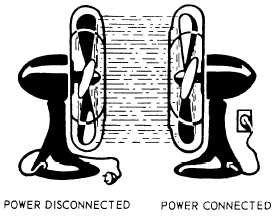
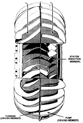
The principle of fluid drive is shown in figure 2-7.As two fans face each other, the speed of rotation of onefan makes the other fan rotate. When the speed of onefan is changed from medium to low, power is lost at lowspeeds; but, if the fan speed increases from medium tohigh, the speed of the driven fan picks up.Torque ConverterThe torque converter is a form of and has replacedthe fluid coupling. Most automatic transmissions usedin automotive and construction equipment have torqueconverters.The torque converter consists of three parts: thepump (driving member), the turbine (driven member),and the stator (reaction member), all with curved vanes.The stator is located between the load and the powersource to act as a fulcrum and is secured to the torqueconverter housing. Figure 2-8 shows a cutaway view ofa torque converter and the directional flow of oil. Thepump throws out oil in the same direction in which thepump is turning. As the oil strikes the turbine blade, itforces the turbine to rotate, and the oil is directed towardthe center of the turbine. Then the oil leaves the turbineand moves in a direction opposite to that of the pump.As the oil strikes the stator, it is redirected to flow in thesame direction as the pump to add its force to that of thepump. Torque is multiplied by the velocity and directiongiven to the oil by the pump, plus the velocity anddirection of the oil entering the pump from the stator.Planetary GearsAutomatic transmissions use a system of planetarygears to enable the torque from the torque converter tobe used efficiently.Figure 2-7.—Principle of fluid drive.Figure 2-8.—Torque converter.Planetary units are the heart of the automatictransmission. The four parts that make up the planetarygear system are as follows: the sun gear, the ring (orinternal) gear, the planet pinions, and the planet carrier.The sun gear is the center of the system. The termplanet fits these pinions and gears, because they rotatearound the sun gear, as shown in figure 2-9. The ringgear, or internal gear, is so-called because of its shapeand internal teeth.An advantage of the planetary gear system is that itis compact. Additionally, in the planetary system moreteeth make contact to carry the load. The reason for thisis that each gear of the planetary system usually mesheswith at least two other gears. Because the gears arealways in mesh, none of the teeth are damaged as a resultof teeth clashing or a partial mesh. However, the majoradvantage of the planetary system is the ease of shiftinggears. Planetary gears, set in automatic transmissions,are shifted without any special skill required by theoperator.2-6
Integrated Publishing, Inc. - A (SDVOSB) Service Disabled Veteran Owned Small Business