However, if the rear wheels should lose traction and begin
to slip, they tend to turn faster than the front wheels. When
this occurs, the sprag unit automatically engages. This
action allows the front wheels to also drive the vehicle.
The sprag unit simply provides an automatic means of
engaging the front wheels in drive for more traction.
Power Takeoffs
Power takeoffs, commonly known as the PTO, are
attachments in the power train for power to drive auxiliary
accessories.
They are attached to the transmission,
auxiliary transmission, or transfer case. A common type
of PTO is the single-gear, single-speed type that is bolted
to an opening provided in the side of the transmission case,
as shown in figure 2-10. The sliding gear of the PTO
meshes with the transmission countershaft gear. The
operator can move a shifter shaft control lever to slide the
gear in and out of mesh with the countershaft gear. The
spring-loaded ball holds the shifter shaft in position.
On some vehicles, PTO units have gear
arrangements that give two speeds forward and one in
reverse.
Several forward speeds and reverse gear
arrangements are usually provided in PTO units used to
operate winches and hoists.
PROPELLER SHAFT ASSEMBLIES
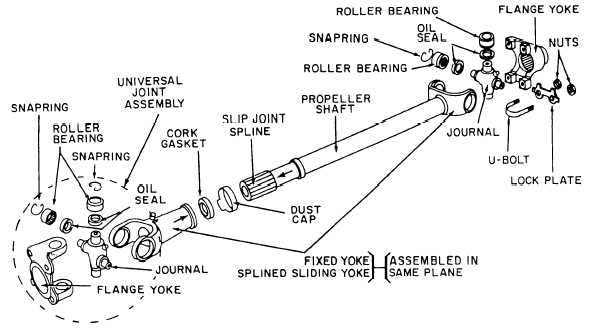
The propeller shaft assembly (fig. 2-12) consists of
a propeller shaft, commonly know as the drive shaft, a
slip joint, and two or more universal joints. This
assembly provides a path through which power is
transmitted from the transmission to the drive axle
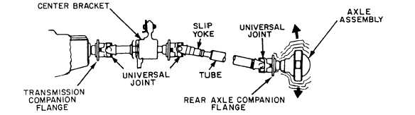
assemblies or auxiliary equipment. Vehicles, having a
long wheel base, are equipped with a propeller shaft that
extends from the transmission or transfer case to a center
support bearing and a propeller shaft that extends from
the center support bearing to the rear axle (fig. 2-13).
Figure 2-12.—Propeller shaft assembly.
Figure 2-13.—Propeller shaft assembly with center support bearing.
2-9