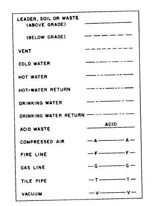
contours, boundaries, roads, utilities, trees, structures,references, and other significant physical features onor near the construction site.A plan and profile sheet (fig. 15-6) and a typicalcross section (fig. 15-7) are other information foundon a site plan.SymbolsSymbols used in drawings are as follows:. A contour line shows us an imaginary line,representing a constant elevation on the earth’s surface.Blueprints, or plans, use contour lines to show the finalproposed elevations.. Existing contour lines identify the existing ele-vations (fig. 15-8). Existing and proposed elevations areused to figure cut-and-fill operations..Proposed contour lines are those we work to-ward, You use them to visualize the finished product(fig. 15-8)..Utility symbols identify utility lines. The sym-bols for pipe are shown in figure 15-9. Once all theFigure 15-9.—Utility symbols for piping.Figure 15-8.—Existing and proposed contour lines.15-7
Integrated Publishing, Inc. - A (SDVOSB) Service Disabled Veteran Owned Small Business