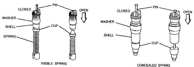
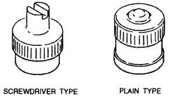
Figure 3-12.—Valve cores.UNDERINFLATED.— An underinflated tire isshown in figure 3-11, view B. This tire does not containenough air for its size and the load it must carry. It flexesexcessively in all directions and gets hot. In time, theheat weakens the cords in the tire, and it blows out.Underinflation also causes tread edges to scuff the roadthat puts uneven wear on the tread and shortens tire life.Never run a tire flat, or nearly flat, unless the tacticalsituation in combat requires it. When run flat for even ashort distance or almost flat for a long distance, the tiremay be ruined beyond repair.OVERINFLATED.— An overinflated tire isshown in figure 3-11, view C. Too much air pressurealso causes tire failure. Excessive pressure prevents thetire from flexing enough and causes it to be constantlysubjected to hard jolts. When an overinflated tire hits astone or rut, the cords may snap and cause a break in thecord body. The center of the tread wears more rapidlyand does not permit equal wear across the entire tread.Hard riding from too much air pressure also increaseswear and tear on the vehicle.ValvesFor speed and convenience during inflation, valvestems should be readily accessible. They should beproperly centered in the valve holes and slots to preventscraping against the brake drums. They should be placedso the valves extend through the wheels. Valves on theinside duals should point away from the vehicle, and thevalves on the outside duals should point toward thevehicle. On dual wheels, the valve of the outside dual isplaced 180 degrees from the inside valve for speed andconvenience in checking pressures and inflation. Withthis arrangement, the locations of the valves are alwaysknown even when you are checking them in the dark.Spare tires should be mounted so that the valve isaccessible for checking and inflating.VALVE CORES.— The valve core (fig. 3-12) isthat part of the valve that is screwed into the valve stemand permits air, under pressure, to enter, but prevents itfrom escaping. Two types of valve cores and two sizesof each type are in use today. The two types are thevisible spring type and the concealed spring type. Thetwo types are interchangeable. Two sizes are providedfor the standard bore and the large bore valve stems. Thecore shell has a rubber washer that provides an airtightseal against the tapered seat inside the stem. Directlybelow the shell is a cup that contains a rubber seat,which, in the closed position, is forced against thebottom of the shell, forming an airtight seal. The pin ontop of the valve core, when pushed down, forces the cupaway from the shell, permitting air to flow.VALVE CAPS.— The valve cap (fig. 3-13) is alsoa component part of the valve and is screwed onto theend of the stem, providing a second airtight seal. Thecap also protects the threads on the end of the stem andFigure 3-13.—Valve caps.3 -8
Integrated Publishing, Inc. - A (SDVOSB) Service Disabled Veteran Owned Small Business