valve allows normal flow in one direction and
restricted flow in the other. It is often referred
to as a one-way restrictor.
Figure 6-26, view A, shows a cone-type orifice
check valve. When sufficient fluid pressure is
applied at the inlet port, it overcomes spring
tension and moves the cone off of its seat. The
two orifices (2) in the illustration represent several
openings located around the slanted circumference
of the cone. These orifices allow free flow of fluid
through the valve while the cone is off of its seat.
When fluid pressure is applied through the outlet
port, the force of the fluid and spring tension
move the cone to the left and onto its seat. This
action blocks the flow of fluid through the valve,
except through the orifice (1) in the center of the
cone. The size of the orifice (in the center of the
cone) determines the rate of flow through the
valve as the fluid flows from right to left.
Figure 6-26, view B, shows a ball-type orifice
check valve. Fluid flow through the valve from
left to right forces the ball off of its seat and
allows normal flow. Fluid flow through the valve
in the opposite direction forces the ball onto its
seat. Thus, the flow is restricted by the size of the
orifice located in the housing of the valve.
NOTE: The direction of free flow through the
orifice check valve is indicated by an arrow
stamped on the housing.
SHUTTLE VALVE
In certain fluid power systems, the supply of
fluid to a subsystem must be from more than one
source to meet system requirements. In some
systems an emergency system is provided as a
source of pressure in the event of normal system
failure. The emergency system will usually actuate
only essential components.
The main purpose of the shuttle valve is to
isolate the normal system from an alternate or
emergency system. It is small and simple; yet, it
is a very important component.
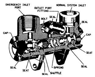
Figure 6-27 is a cutaway view of a typical
shuttle valve. The housing contains three ports—
normal system inlet, alternate or emergency
system inlet, and outlet. A shuttle valve used to
operate more than one actuating unit may contain
additional unit outlet ports. Enclosed in the
housing is a sliding part called the shuttle. Its
purpose is to seal off either one or the other inlet
ports. There is a shuttle seat at each inlet port.
6-18
Figure 6-27.—Shuttle valve.
When a shuttle valve is in the normal
operation position, fluid has a free flow from the
normal system inlet port, through the valve, and
out through the outlet port to the actuating unit.
The shuttle is seated against the alternate system
inlet port and held there by normal system
pressure and by the shuttle valve spring. The
shuttle remains in this position until the alternate
system is activated. This action directs fluid under
pressure from the alternate system to the shuttle
valve and forces the shuttle from the alternate
system inlet port to the normal system inlet port.
Fluid from the alternate system then has a free
flow to the outlet port, but is prevented from
entering the normal system by the shuttle, which
seals off the normal system port.
The shuttle may be one of four types: (1)
sliding plunger, (2) spring-loaded piston, (3)
spring-loaded ball, or (4) spring-loaded poppet.
In shuttle valves that are designed with a spring,
the shuttle is normally held against the alternate
system inlet port by the spring.
TWO-WAY VALVES
The term two-way indicates that the valve
contains and controls two functional flow control
ports-an inlet and an outlet. A two-way, sliding
spool directional control valve is shown in figure
6-23. As the spool is moved back and forth, it
either allows fluid to flow through the valve or
prevents flow. In the open position, the fluid
enters the inlet port, flows around the shaft of
the spool, and through the outlet port. The spool
cannot move back and forth by difference of