spool assembly consists of a valve spool (10) and
a spring (4).
Fluid under main pressure enters the inlet port
(11) and under all conditions is free to flow
through the valve and the outlet port (5). (Either
port 5 or port 11 maybe used as the high-pressure
port.)
Figure 6-19, view A, shows the valve in the
open position. In this position, the pressure in the
reduced-pressure outlet port (6) has not reached
the preset operating pressure of the valve. The
fluid also flows through passage 8, through smaller
passage 9 in the center of the valve spool, and into
chamber 12. The fluid pressure at outlet port 6
is therefore distributed to both ends of the spool.
When these pressures are equal the spool is hydrau-
lically balanced. Spring 4 is a low-tension spring
and applies only a slight downward force on the
spool. Its main purpose is to position the spool
and to maintain opening 7 at its maximum size.
As the pressure increases in outlet port 6 (fig.
16, view B), this pressure is transmitted through
passages 8 and 9 to chamber 12. This pressure also
acts on the pilot valve poppet (1). When this
pressure increases above the preset operating
pressure of the valve, it overcomes the force of
pilot valve spring 2 and unseats the poppet. This
allows fluid to flow through the drain port (15).
Because the small passage (9) restricts flow into
chamber 12, the fluid pressure in the chamber
drops. This causes a momentary difference in
pressure across the valve spool (10) which allows
fluid pressure acting against the bottom area of
the valve spool to overcome the downward force
of spring 4. The spool is then forced upward until
the pressures across its ends are equalized. As the
spool moves upward, it restricts the flow through
opening 7 and causes the pressure to decrease in
the reduced pressure outlet port 6. If the pressure
in the outlet port continues to increase to a value
above the preset pressure, the pilot valve will open
again and the cycle will repeat. This allows the
spool valve to move up higher into chamber 12;
thus further reducing the size of opening 7.
These cycles repeat until the desired pressure is
maintained in outlet 6.
When the pressure in outlet 6 decreases to a
value below the preset pressure, spring 4 forces
the spool downward, allowing more fluid to flow
through opening 7.
COUNTERBALANCE VALVE
The counterbalance valve is normally located
in the line between a directional control valve and
the outlet of a vertically mounted actuating
cylinder which supports weight or must be held
6-14
in position for a period of time. This valve serves
as a hydraulic resistance to the actuating cylinder.
For example, counterbalance valves are used in
some hydraulically operated forklifts. The valve
offers a resistance to the flow from the actuating
cylinder when the fork is lowered. It also helps
to support the fork in the UP position.
Counterbalance valves are also used in air-
launched weapons loaders. In this case the valve
is located in the top of the lift cylinder. The valve
requires a specific pressure to lower the load. If
adequate pressure is not available, the load cannot
be lowered. This prevents collapse of the load due
to any malfunction of the hydraulic system.
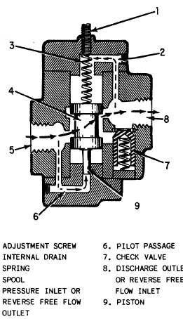
One type of counterbalance valve is illustrated
in figure 6-20. The valve element is a balanced
spool (4). The spool consists of two pistons
permanently fixed on either end of a shaft. The
inner surface areas of the pistons are equal;
therefore, pressure acts equally on both areas
regardless of the position of the valve and has no
effect on the movement of the valve—hence, the
term balanced. The shaft area between the two
pistons provides the area for the fluid to flow
Figure 6-20.—Counterbalance valve.